1. Product Overview
The Walfront Scanner Line Generator is a compact hardware device designed to simulate the classic scanline effect found on older CRT displays. This enhances the visual fidelity of retro games when played on modern LCD or LED monitors, providing a more authentic and nostalgic gaming experience. It is a general-purpose scan line video effect generator for VGA connections.

2. Specifications
| Feature | Description |
|---|---|
| Model | VC005 |
| Interface | VGA |
| Material | Metal, Plastic |
| Item Weight | 0.704 ounces (approx. 20g) |
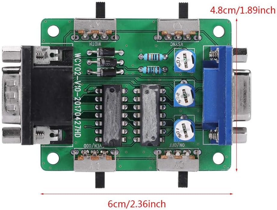
| Dimensions | Approx. 6cm x 4.8cm (2.36 x 1.89 inches) |
| Power Source | Corded Electric (via VGA, no external power needed) |
| Controller Type | Button Control (Switches and Potentiometers) |

3. Setup Guide
3.1 Connecting the Device
The Scanner Line Generator is designed for simple plug-and-play operation. No external power supply is required as it draws power directly from the VGA connection.
- Identify the VGA output from your retro gaming console, PC, or other video source.
- Connect the VGA cable from your video source to the "Vedio In" port on the Scanner Line Generator.
- Connect a VGA cable from the "Vedio Out" port on the Scanner Line Generator to your modern LCD monitor or TV.
- Ensure all connections are secure.

4. Operating Instructions
4.1 Understanding the Controls
The device features several switches and potentiometers to fine-tune the scanline effect. Refer to the diagram and table below for a description of each control.

| Switch/Potentiometer | Function |
|---|---|
| A (ON/OFF) | Master switch for the scan line effect. Toggles the effect on or off. |
| B (RGB) | Three potentiometers for debugging and adjusting red, green, and blue tricolor components. Use a small screwdriver to adjust. |
| C (WIDTH) | Adjusts the width of the scan lines (double or single scan line effect). |
| D (VSYNC) | Resolution adapter switch. May be required to change resolution for optimal effect. |
| E (EVEN/ODD) | Toggles between odd or even scan line patterns. |
4.2 Adjusting Scanline Effects
Once connected, power on your video source and display. The scanline generator will automatically apply the effect. Use the switches and potentiometers to customize the appearance:
- Toggle switch A to enable or disable the scanline effect.
- Experiment with switch C (WIDTH) to choose between a subtle or more pronounced scanline appearance.
- If the image appears distorted or incorrect, try adjusting switch D (VSYNC).
- Switch E (EVEN/ODD) can alter the pattern of the scanlines, which might be useful for specific game types or preferences.
- The B (RGB) potentiometers are for advanced color calibration. Adjust these carefully with a small screwdriver if you notice color imbalances.

5. Maintenance
The Walfront Scanner Line Generator requires minimal maintenance. To ensure longevity and optimal performance:
- Keep the device in a dry, dust-free environment.
- Clean the exterior with a soft, dry cloth. Avoid using liquid cleaners or abrasive materials.
- Do not expose the device to extreme temperatures or direct sunlight.
- Handle the switches and ports gently to prevent damage.
6. Troubleshooting
| Problem | Possible Cause | Solution |
|---|---|---|
| No scanline effect / Device not working | Loose VGA connections; Switch A (ON/OFF) is off; Incompatible resolution; Finicky switches. | Ensure all VGA cables are securely connected. Toggle switch A to the ON position. Try adjusting switch D (VSYNC). Gently jiggle or firmly press the switches to ensure they engage properly. |
| Image distortion or incorrect colors | Incorrect RGB calibration; Resolution mismatch. | Adjust the B (RGB) potentiometers slightly with a small screwdriver. Try adjusting switch D (VSYNC). Ensure your display is set to a compatible resolution. |
| Scanlines appear too thick or too thin | WIDTH switch setting. | Toggle switch C (WIDTH) to change between double or single scanline effects. |
| Scanlines are not uniform or appear odd | EVEN/ODD switch setting. | Toggle switch E (EVEN/ODD) to alternate the scanline pattern. |
7. Warranty and Support
7.1 Warranty Information
For information regarding product warranty, please refer to the terms and conditions provided at the time of purchase or contact your retailer. Walfront is committed to providing quality products and customer satisfaction.
7.2 Customer Support
If you encounter any issues not covered in this manual or require further assistance, please contact Walfront customer support through the platform where you purchased the product. You can also visit the official Walfront store on Amazon for more information and contact options: Walfront Amazon Store.
