Introduction
This manual provides detailed instructions for the proper installation, operation, and maintenance of your DROK 15W+15W 2.0 Dual Channel Audio Amplifier Board. Please read this manual thoroughly before use to ensure optimal performance and safety.

Image: DROK 15W+15W PAM8620 Dual Channel Audio Amplifier Board.
Safety Precautions
- Ensure the power supply voltage is within the specified DC 8-26V range. Incorrect voltage can damage the device.
- Avoid short circuits on the output terminals.
- Do not expose the board to moisture or extreme temperatures.
- Handle with care to prevent damage to electronic components.
- Disconnect power before making any connections or adjustments.
Product Features
The DROK 15W+15W Audio Amplifier Board is designed for high-fidelity audio applications, offering robust performance and protective features:
- Wide Operating Voltage: DC 8-26V, compatible with 12V and 24V power sources.
- High Output Power: Delivers 15W stereo (24V 8ohm) or 10W stereo (12V 8 ohm). Automatically limits power to 15W for 4 ohm or 2 ohm speakers.
- Premium Construction: Features a black immersion gold circuit board, PAM8620 chip, imported KEMET speaker capacitors, large-capacity filter capacitors, black copper terminal blocks, and gold-plated audio input terminals.
- High Performance: Class D power amplifier module with over 90% efficiency, general harmonic distortion noise less than 0.2%, low quiescent current, and noise suppression.
- Comprehensive Protection: Includes input reverse connection protection, short circuit protection, over-heat protection, overcurrent protection, overvoltage protection, and undervoltage protection. EMI is also allowed to pass.
- Additional Functions: Supports external mute function (MUTE: High level mute, factory default low level) and external shutdown (SD: chip shuts down at low electricity level, factory default high electricity level).
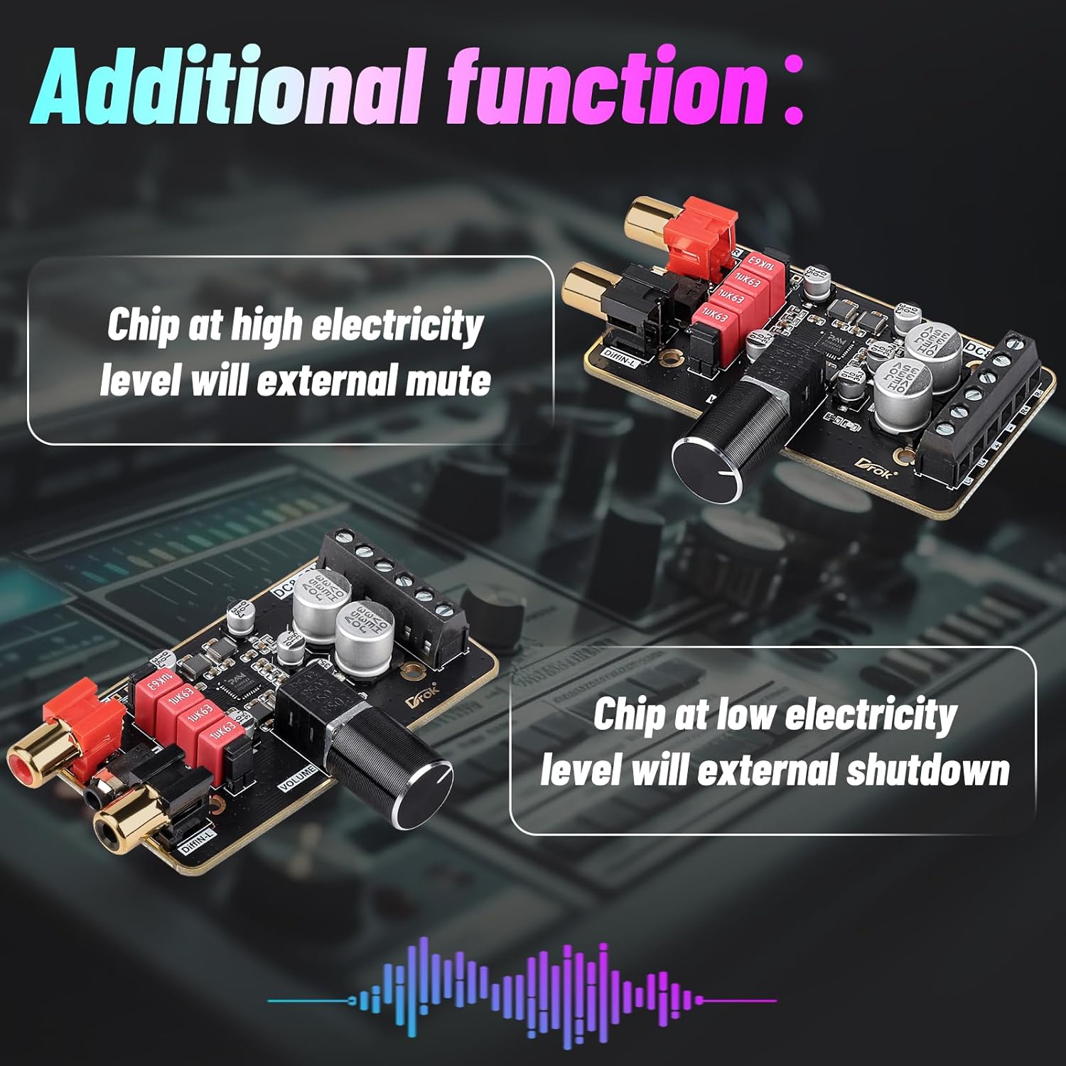
Image: Detailed view of the PAM8620 chip and high-quality components.

Image: Visual representation of the amplifier board's safety protection features.

Image: Illustration of the amplifier board's high performance characteristics.
Specifications
| Brand | DROK |
| Model Number | 2001711003 |
| Working Voltage | DC 8-26V |
| Output Power | 15W + 15W Stereo (24V 8ohm) / 10W + 10W Stereo (12V 8 ohm) |
| Speaker Impedance | 4-8 Ohm (Power automatically limited to 15W for 4 or 2 ohm speakers) |
| Efficiency | >90% (Class D) |
| Harmonic Distortion Noise | <0.2% |
| Dimensions | 76mm x 42mm x 13mm (approx. 3 x 1.65 x 0.51 inches) |
| Weight | 1.44 ounces |

Image: Physical dimensions of the amplifier board.
Package Contents
The package typically includes:
- 1x DROK 15W+15W PAM8620 Audio Amplifier Board
- (Note: Power supply and speakers are not included and must be purchased separately.)
Setup
Follow these steps to set up your amplifier board:
- Power Connection: Connect a DC 8-26V power supply to the "DC8-26V" terminal block. Ensure correct polarity (DC power+ and DC power-).
- Speaker Connection: Connect your speakers to the output terminal blocks. The right channel speaker connects to "Right channel speaker" terminals (R+ and R-), and the left channel speaker connects to "Left channel speaker" terminals (L+ and L-). Ensure correct polarity for each speaker.
- Audio Input:
- 3.5mm Audio Cable (Single-ended input): Connect a 3.5mm audio cable to the "Single input port". If using this input, ensure the two jumpers (labeled "SE-IN") are removed.
- RCA Input (Differential input): Connect RCA cables to the "DiffIN-R" (Right) and "DiffIN-L" (Left) ports. This input is for audio equipment supporting differential output. If using this input, ensure the two jumpers (labeled "SE-IN") are installed.

Image: Overview of the amplifier board's input and output terminals.

Image: A wiring example demonstrating connection of a 3.5mm audio source and two 15W speakers to the amplifier board, powered by a 12V DC battery.
Operating Instructions
Once all connections are securely made and power is applied:
- Volume Adjustment: Use the "VOLUME" knob to adjust the audio output level. Rotate clockwise to increase volume, and counter-clockwise to decrease volume.
- Mute Function: The board supports an external mute function. By default, the mute is at a low level. A high-level signal applied to the MUTE pin will mute the audio output.
- Shutdown Function: The board supports an external shutdown function. By default, the shutdown is at a high electricity level. A low-level signal applied to the SD pin will shut down the chip.
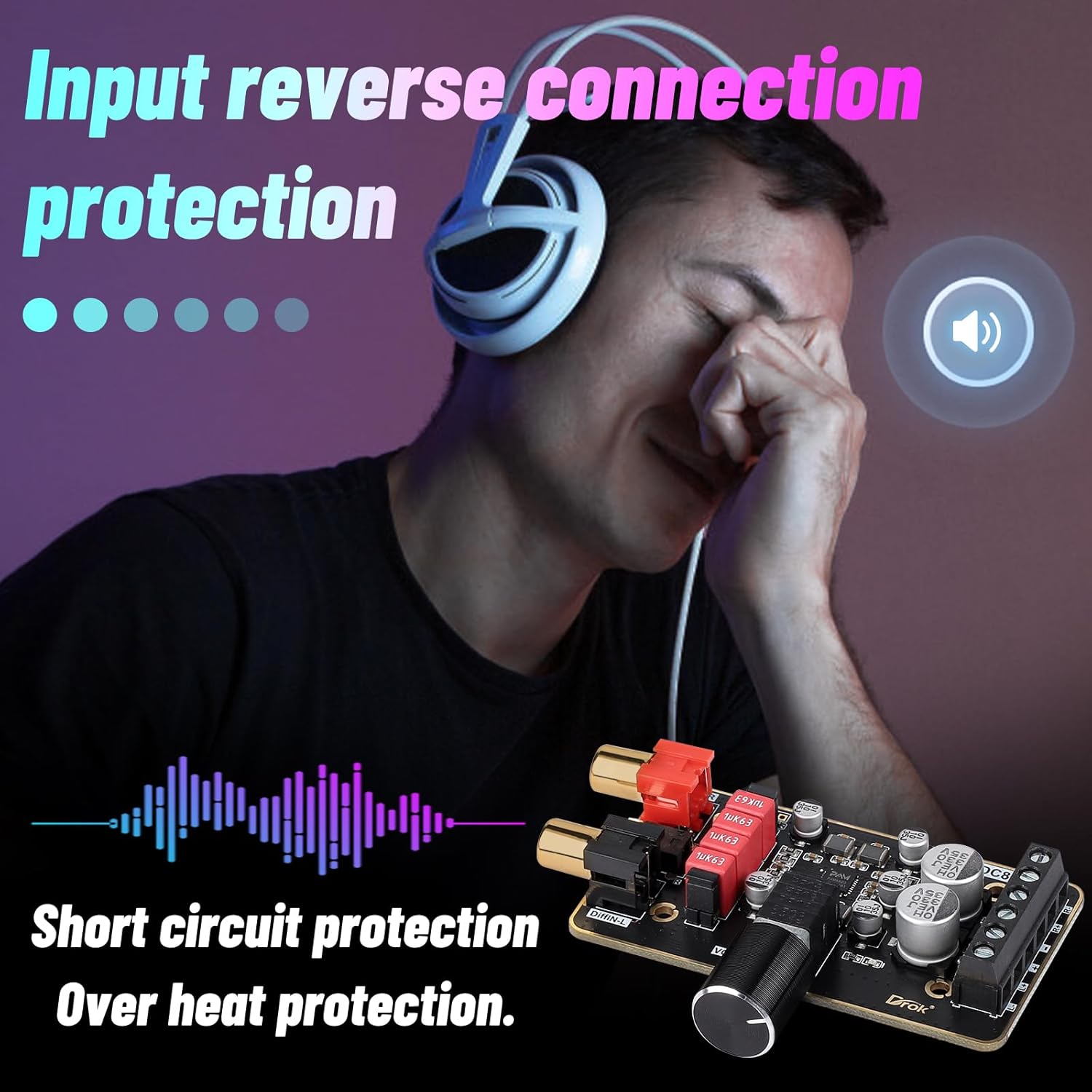
Image: Explanation of how to use the external mute and shutdown features.
Maintenance
- Keep the amplifier board clean and free from dust. Use a soft, dry cloth for cleaning.
- Ensure adequate ventilation around the board to prevent overheating, especially during prolonged use at high volumes.
- Regularly check all connections for tightness and corrosion.
- Avoid placing heavy objects on the board or subjecting it to physical shock.
Troubleshooting
| Problem | Possible Cause | Solution |
|---|---|---|
| No sound output | Incorrect power connection, loose speaker wires, incorrect audio input selection (jumpers), muted state, or low volume. | Verify power supply and polarity. Check all speaker and audio input connections. Ensure correct jumper settings for single-ended or differential input. Adjust volume. Check mute/shutdown status. |
| Distorted audio | Input signal too high, speaker impedance mismatch, or faulty speaker. | Reduce input signal level. Ensure speakers are within the recommended 4-8 Ohm range. Test with different speakers. |
| Overheating | Lack of ventilation, prolonged high-volume use, or short circuit. | Ensure proper airflow around the board. Reduce volume or usage time. Check for short circuits. |
| Humming or noise | Ground loop, interference from other electronics, or poor quality audio cables. | Ensure proper grounding. Separate audio cables from power cables. Use shielded audio cables. Consider a ground loop isolator if necessary. |
Warranty and Support
For warranty information or technical support, please refer to the official DROK website or contact your retailer. Keep your purchase receipt for warranty claims.