1. Introduction
The Midiplus SPY is a versatile MIDI pedal controller designed to convert analog expression and switch pedal signals into USB and standard MIDI signals. This device allows seamless integration of your favorite expression and switch pedals with your digital audio workstation (DAW) or other MIDI-compatible equipment. Its robust metal construction ensures durability, while its intuitive design provides straightforward operation for musicians and producers.
2. Key Features
- USB Connectivity: Converts expression and switch pedal signals into USB MIDI data for computer-based music production.
- Expression Pedal Input: Compatible with most expression pedals and supports calibration for precise control.
- Switch Pedal Input: Connects to two switch pedals to send program change (up/down) messages.
- MIDI Input/Output: Standard 5-pin DIN MIDI ports for compatibility with a wide range of MIDI devices.
- Assignable CC Value: The expression pedal can be configured to send specific MIDI Control Change (CC) values.
- User Interface: Features a 3-bit 7-segment LED display and a rotary encoder with press function for easy navigation and parameter adjustment.
- Durable Construction: Housed in a metal shell with anti-skid pads for stability.
3. Package Contents
Please ensure all items are present in the package:
- Midiplus SPY MIDI Pedal Controller
- USB Cable
- Instruction Manual (this document)
4. Controls and Connections

Figure 4.1: Top View of Midiplus SPY Controller. This image displays the top panel of the Midiplus SPY, featuring the 3-bit 7-segment LED display, the rotary encoder with press function, and the "SPY" branding.
4.1 Front Panel
- LED Display: A 3-bit 7-segment display shows current parameter values or settings.
- Rotary Encoder: Used for navigating menus, adjusting values, and confirming selections by pressing down.
4.2 Side Panels and Rear Connections

Figure 4.2: Left Side View. This image shows the left side of the Midiplus SPY, highlighting the MIDI IN port and the Expression Pedal input jack.
- MIDI IN (5-pin DIN): Connects to other MIDI devices for receiving MIDI data.
- Expression Pedal Input (1/4" TRS Jack): Connect your expression pedal here.
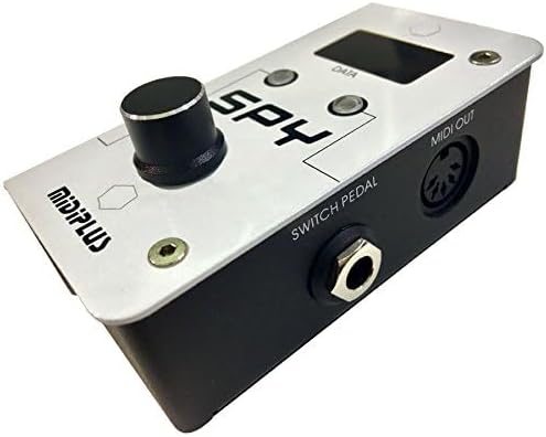
Figure 4.3: Right Side View. This image displays the right side of the Midiplus SPY, showing the Switch Pedal input jack and the MIDI OUT port.
- Switch Pedal Input (1/4" TRS Jack): Connect your switch pedal(s) here. Supports two switch pedals via a Y-cable.
- MIDI OUT (5-pin DIN): Sends MIDI data to other MIDI devices.

Figure 4.4: Rear View. This image shows the rear panel of the Midiplus SPY, featuring the USB port and the 9V DC power connector.
- USB Port (Type B): Connects the SPY to your computer for USB MIDI communication and power.
- DC 9V / 50mA Power Connector: Optional external power input. The unit can also be bus-powered via USB.
5. Setup
5.1 Connecting to a Computer (USB MIDI)
- Connect one end of the supplied USB cable to the USB port on the SPY controller.
- Connect the other end of the USB cable to an available USB port on your computer.
- The SPY is a class-compliant USB MIDI device and typically does not require special drivers for Windows (7/10) or macOS. Your operating system should automatically recognize it.
- Open your Digital Audio Workstation (DAW) or MIDI software and ensure the "Midiplus SPY" is recognized as a MIDI input/output device in your MIDI settings.
5.2 Connecting Pedals
- Expression Pedal: Connect your expression pedal (TRS cable recommended) to the "Expression Pedal" input jack.
- Switch Pedal: Connect your switch pedal(s) to the "Switch Pedal" input jack. This input supports a single switch pedal or two switch pedals using a TRS Y-cable.
5.3 External Power (Optional)
If not powered via USB, connect a 9V DC (center-negative, 50mA minimum) power adapter to the "DC 9V / 50mA" input.
6. Operation
6.1 Expression Pedal Control
The expression pedal input converts the analog position of your pedal into a MIDI Control Change (CC) message.
- Default CC Value: The expression pedal typically defaults to MIDI CC 7 (Volume) or CC 11 (Expression).
- Assigning CC Value:
- Press and hold the rotary encoder until the LED display changes to show the current CC number.
- Rotate the encoder to select the desired MIDI CC number (0-127).
- Press the encoder again to confirm the selection.
- Pedal Calibration: If your expression pedal does not respond correctly or has an uneven range, perform a full sweep (heel to toe) after assigning the CC value to ensure the SPY learns the full range.
6.2 Switch Pedal Control (Program Change)
The switch pedal input is designed to send MIDI Program Change (PC) messages. When a dual switch pedal is connected via a TRS Y-cable, one switch typically increments the program number, and the other decrements it. The SPY is hardwired to send sequential PC signals (e.g., PC 32, PC 33, PC 34).
- Connect your switch pedal(s) to the "Switch Pedal" input.
- Pressing a switch will send a Program Change message.
- In your DAW or MIDI software, ensure that the receiving instrument or effect is configured to respond to Program Change messages on the correct MIDI channel. Note that some DAWs may require specific mapping or scripts to interpret these sequential PC messages as simple up/down toggles.
6.3 MIDI Input/Output
The MIDI IN and MIDI OUT ports allow the SPY to integrate with traditional MIDI hardware.
- MIDI IN: Connect a MIDI cable from the MIDI OUT of another device to the SPY's MIDI IN to receive MIDI data.
- MIDI OUT: Connect a MIDI cable from the SPY's MIDI OUT to the MIDI IN of another device to send MIDI data generated by the pedals or received via USB.
7. Maintenance
- Cleaning: Use a soft, dry cloth to clean the exterior of the unit. Do not use liquid cleaners or solvents.
- Storage: Store the unit in a cool, dry place away from direct sunlight and extreme temperatures.
- Handling: Avoid dropping the unit or subjecting it to strong impacts.
8. Troubleshooting
8.1 No Power/Unit Not Turning On
- Ensure the USB cable is securely connected to both the SPY and your computer.
- If using an external power adapter, verify it is a 9V DC (center-negative) adapter and is properly connected to a working power outlet.
- Try a different USB port or power outlet.
8.2 SPY Not Recognized by Computer/DAW
- Disconnect and reconnect the USB cable.
- Restart your computer and DAW.
- Check your DAW's MIDI settings to ensure the "Midiplus SPY" is enabled as an input/output device.
- Try a different USB cable or USB port.
8.3 Expression Pedal Not Responding or Inaccurate
- Ensure the expression pedal is correctly connected to the "Expression Pedal" input.
- Verify the expression pedal is compatible with the SPY (most standard expression pedals are).
- Perform pedal calibration as described in Section 6.1.
- Check the assigned MIDI CC value on the SPY and in your DAW to ensure they match the parameter you intend to control.
8.4 Switch Pedal Not Working as Expected (Program Change)
- Confirm the switch pedal is connected to the "Switch Pedal" input.
- Understand that the SPY sends sequential MIDI Program Change messages, not simple on/off CC messages. Your DAW or receiving device must be configured to interpret these PC messages.
- If using a dual switch pedal, ensure you are using a TRS Y-cable if required by your pedal.
- Check the polarity switch on your switch pedal, if available, as incorrect polarity can prevent proper operation.
9. Specifications
| Model | SPY |
| Dimensions (L x W x H) | 9.7 x 5.11 x 3.4 cm (3.82 x 2.01 x 1.34 inches) |
| Weight | 240 g (0.53 lbs) |
| Material | Metal shell |
| Connectivity | USB (Type B), MIDI IN (5-pin DIN), MIDI OUT (5-pin DIN) |
| Inputs | 1/4" TRS Expression Pedal, 1/4" TRS Switch Pedal |
| Power Requirements | USB Bus Power or DC 9V / 50mA (center-negative) |
| Display | 3-bit 7-segment LED |
| Compatible OS | Windows 7/10, macOS |
10. Support
For technical assistance or further inquiries, please visit the official Midiplus website or contact their customer support. Keep your purchase receipt for any warranty claims.


