1. Introduction
This manual provides detailed instructions for the installation, operation, and maintenance of your ZEROXCLUB Digital Wireless Backup Camera System Kit. This system is designed to enhance visibility and safety for various vehicles, including RVs, trucks, trailers, buses, campers, and 5th wheels.
2. Package Contents
Please verify that all components listed below are included in your package:
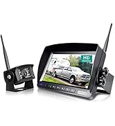
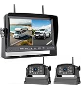
- 7-inch LCD Wireless Monitor
- Wireless Rear View Camera
- Fixed Bracket
- Sunshade for Monitor
- Camera Bracket
- Suction Cup Mount
- Power Cords (for monitor and camera)
- Installation Kits (screws, connectors)
- Antennas (for monitor and camera)
- Car Charger

3. Product Overview
3.1 Key Features
- Digital Wireless Signal: Provides stable and clear transmission up to 100ft and at speeds up to 85 mph, minimizing interference.
- HD 1080P 7-inch Monitor: Features a 1080P display with advanced IPS technology for fast response and clear images. Includes auto-dimming and a suction cup mount.
- IP69 Waterproof Camera: Equipped with 18 infrared lights and a CCD sensor for superior night vision. The camera is IP69 rated for water and dust resistance, ensuring durability in various weather conditions.
- 149° Wide View Angle: Offers an expansive field of view to enhance safety during reversing and maneuvering.
- Wide Application: Compatible with 12-24V DC power systems, suitable for RVs, semi-trailers, box trucks, 5th wheels, trailers, and buses.
3.2 Component Details


4. Installation Guide
4.1 Camera Installation
- Choose Mounting Location: Select a suitable location at the rear of your vehicle (RV, truck, trailer, etc.) that provides a clear view and allows for secure mounting. The camera can be mounted using either the vertical or horizontal bracket.
- Secure the Camera: Use the provided screws and fixed bracket to securely attach the camera to the chosen location. Ensure the antenna is positioned for optimal signal transmission.
- Power Connection:
- Option 1 (Reversing Activation): Connect the camera's red power wire to your vehicle's taillight or reversing light power source. Connect the black ground wire to a suitable ground point on the vehicle chassis. This method allows the camera to power on automatically when the vehicle is in reverse.
- Option 2 (Constant Power): Connect the camera's red power wire to a running light or an accessory power source that is always on when the vehicle is operating. Connect the black ground wire to a suitable ground point. This method keeps the camera continuously powered.

4.2 Monitor Installation
- Mount the Monitor:
- Suction Cup Mount: Attach the suction cup mount to a clean, smooth surface on your windshield. Secure the monitor to the mount.
- Dashboard Mount: Use the provided dashboard mount to place the monitor on your dashboard. Ensure it is stable and does not obstruct your view.
- Power Connection: Plug the monitor's car charger into your vehicle's cigarette lighter socket. The monitor will power on automatically.

5. Operating Instructions
5.1 Initial Power-Up
Once the camera and monitor are correctly installed and powered, the system should automatically establish a wireless connection. The camera's view will appear on the monitor.
5.2 Monitor Controls
The monitor features several buttons for control and adjustment:
- POWER: Turns the monitor on or off.
- +/-: Adjusts brightness or navigates menu options.
- CH: Switches between camera channels if multiple cameras are connected.
- MENU: Accesses the monitor's settings menu.
- SEL: Selects options within the menu.

5.3 Adjusting Camera View
The camera's bracket allows for 360-degree adjustment. Loosen the bracket screws, adjust the camera to the desired angle, and then tighten the screws to secure it.

6. Maintenance
- Cleaning: Regularly clean the camera lens and monitor screen with a soft, damp cloth. Avoid abrasive cleaners that could scratch surfaces.
- Cable Inspection: Periodically check all power connections and cables for signs of wear, damage, or loose connections. Ensure waterproof seals are intact.
- Antenna Position: Ensure the antennas on both the camera and monitor are positioned upright and unobstructed for optimal signal reception.
- Storage: If the system will not be used for an extended period, disconnect it from power and store it in a dry, cool place.
7. Troubleshooting
| Problem | Possible Cause | Solution |
|---|---|---|
| No signal on monitor |
|
|
| Image is blurry or distorted |
|
|
| Monitor not turning on |
|
|
8. Specifications
| Feature | Detail |
|---|---|
| Model Number | W01 |
| Screen Size | 7 Inches |
| Display Technology | LCD |
| Voltage | 12-24 Volts DC |
| Optical Sensor Technology | CCD |
| Lens Type | Wide Angle |
| Real Angle of View | 149 Degrees |
| Waterproof Rating | IP69 |
| Connectivity | Wireless |
| Product Dimensions (Monitor) | 5"L x 1.1"W x 3"H |
| Item Weight | 2.65 pounds (total system) |
9. Customer Support and Warranty
For technical assistance, product inquiries, or warranty information, please contact ZEROXCLUB customer support. You can typically find contact details in the product packaging or on the official ZEROXCLUB website.
Based on available information, you can reach out via email for technical support: susanjiing@hotmail.com.
ZEROXCLUB is committed to providing reliable products and support. Please refer to your purchase documentation for specific warranty terms and conditions.


