
1. Introduction
This manual provides essential information for the safe and effective use of your TOPCHANCES Multi-function Compound Slide Table and Drill Bracket. Please read these instructions carefully before assembly, operation, or maintenance to ensure proper function and to prevent injury or damage.
The compound slide table is designed for precise X-Y axis adjustment, making it suitable for various drilling, milling, and positioning tasks, particularly when used with a bench drill or similar machine.
2. Safety Instructions
Always observe basic safety precautions to reduce the risk of personal injury and damage to the equipment.
- Read the Manual: Familiarize yourself with all instructions and warnings before operating the equipment.
- Wear Safety Gear: Always wear appropriate personal protective equipment, including safety glasses, gloves, and hearing protection.
- Secure Workpiece: Ensure the workpiece is securely clamped to the compound slide table before beginning any operation.
- Stable Mounting: Mount the compound slide table securely to a stable workbench or drill press base.
- Clear Work Area: Keep the work area clean and well-lit. Remove any clutter that could interfere with operation.
- Power Disconnection: Disconnect power from any attached machinery (e.g., drill press) before making adjustments or performing maintenance on the slide table.
- Avoid Overloading: Do not exceed the recommended capacity or apply excessive force to the slide table.
3. Product Components
The TOPCHANCES Compound Slide Table consists of several key parts designed for precise movement and secure workpiece holding.

Figure 3.1: Labeled diagram illustrating the main components of the compound slide table.
- Work Table: The main surface where the workpiece is clamped. Features T-slots for securing clamps.
- Fixed Jaw: A stationary component for clamping workpieces.
- Adjustable Ruler: Provides measurement reference for movement.
- Working Guard: Protects internal mechanisms.
- Adjustable Scale: Fine-tuning scale for precise positioning.
- Adjustable Scale Circle: Provides rotational measurement for precise adjustments.
- X-Y Adjustment Knobs: Control the linear movement along the X and Y axes.
- Mounting Base: The bottom section used to secure the slide table to a workbench or drill press.

Figure 3.2: Compound Slide Table with included accessories.

Figure 3.3: Detailed view of the clamping accessories.
4. Setup
Proper setup ensures stability and accuracy during operation.
4.1 Mounting the Compound Slide Table
- Choose a Stable Surface: Select a sturdy workbench or the base of a compatible drill press for mounting.
- Position the Table: Place the compound slide table on the chosen surface, aligning its mounting slots with any available bolt holes on the base.
- Secure with Bolts: Use appropriate bolts and nuts (often included or supplied with your drill press) to firmly attach the slide table to the base. Ensure all fasteners are tightened securely to prevent movement during operation.

Figure 4.1: Compound slide table mounted on a stable base.

Figure 4.2: Detail of the mounting slots for secure attachment.
4.2 Clamping the Workpiece
- Position Workpiece: Place your workpiece on the work table.
- Use T-slot Clamps: Insert the T-slot bolts into the T-grooves on the work table. Position the clamping blocks over the workpiece.
- Tighten Securely: Hand-tighten the nuts on the T-slot bolts to hold the workpiece firmly in place. Ensure the workpiece cannot shift during operation.
5. Operation
The compound slide table allows for precise linear movement along two axes.
5.1 X-Y Axis Adjustment
- Identify Adjustment Knobs: Locate the two adjustment knobs, one for X-axis movement (left-right) and one for Y-axis movement (front-back).
- Coarse Adjustment: For larger movements, turn the respective knob to slide the table to the desired approximate position.
- Fine Adjustment: Use the adjustable scale and scale circle for precise positioning. Each full rotation of the knob corresponds to a specific travel distance (e.g., 1.25mm per circle). The smaller markings (e.g., 0.05mm per cell) allow for very fine adjustments.
- Monitor Scales: Refer to the adjustable ruler and scale markings to track your position and ensure accuracy.
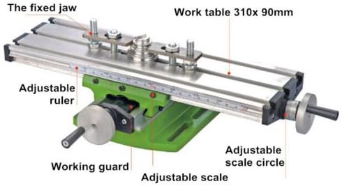
Figure 5.1: Detail of the adjustment knob and scale for fine positioning.

Figure 5.2: Overview of the work table with X-Y scales.
5.2 Using with a Drill Press
When using the compound slide table with a drill press, ensure the drill bit is centered over the desired starting point on your workpiece. Use the X-Y adjustments to precisely position the workpiece for each drilling operation.
6. Maintenance
Regular maintenance will prolong the life and accuracy of your compound slide table.
- Cleaning: After each use, clean the work table and slide mechanisms to remove chips, dust, and debris. Use a brush or compressed air.
- Lubrication: Periodically apply a light machine oil to the lead screws and sliding surfaces to ensure smooth operation and prevent rust. Do not over-lubricate.
- Inspection: Regularly inspect all fasteners for tightness. Check for any signs of wear or damage to the scales or moving parts.
- Storage: Store the compound slide table in a clean, dry environment when not in use.
7. Troubleshooting
If you encounter issues, refer to the following common problems and solutions:
- Movement is Stiff or Jerky:
- Check for debris in the sliding mechanisms. Clean thoroughly.
- Apply a small amount of machine oil to the lead screws and sliding surfaces.
- Ensure no clamps or workpieces are obstructing movement.
- Inaccurate Positioning:
- Verify that the workpiece is securely clamped and not shifting.
- Ensure the compound slide table itself is firmly mounted to its base.
- Check for any play in the adjustment knobs or lead screws.
- Clamps Not Holding Workpiece:
- Ensure the T-slot bolts are correctly seated in the T-grooves.
- Tighten the nuts firmly.
- Verify that the clamping blocks are making proper contact with the workpiece.
8. Specifications
| Feature | Specification |
|---|---|
| Material | Aluminium Alloy |
| Overall Size | 310mm x 90mm x 80mm (approx. 12.2" x 3.5" x 3.1") |
| X-Axis Travel (Route) | 200mm |
| Y-Axis Travel (Route) | 50mm |
| Distance of Grooves | 34mm |
| T-Slot Size | 15mm x 8mm x 6mm (Standard) |
| Scale Travel (per circle) | 1.25mm |
| Scale Travel (per cell) | 0.05mm |
| Manufacturer | TOPCHANCES |
| ASIN | B076X1D158 |
| Power Source (for associated drill) | AC (Alternating Current) |
9. Warranty and Support
Specific warranty details for this product are not provided in the available product information. For warranty claims, technical support, or replacement parts, please contact TOPCHANCES directly through their official channels or the retailer where the product was purchased.
You can visit the TOPCHANCES Store on Amazon for more information.