1. Introduction
This manual provides essential information for the safe and efficient installation, operation, and maintenance of the Allen-Bradley 1756-PA72 ControlLogix Power Supply, Series B. Please read this manual thoroughly before attempting any procedures.

Figure 1: Front view of the Allen-Bradley 1756-PA72 ControlLogix Power Supply. This image shows the main casing with the Allen-Bradley logo and "POWER" indicator light.
2. Safety Information
WARNING: Risk of electric shock. Ensure power is disconnected before installation or maintenance.
Always follow local and national electrical codes. Only qualified personnel should install, operate, or service this equipment. Disconnect all power sources before working on the module or any connected equipment. Use appropriate personal protective equipment (PPE).
3. Setup and Installation
The 1756-PA72 power supply is designed for use with ControlLogix chassis. Ensure the chassis is properly mounted and grounded before installing the power supply.
- Mounting: Slide the power supply into the designated slot in the ControlLogix chassis until it clicks into place. Ensure a secure connection.
- Wiring: Connect the AC input power to the appropriate terminals on the power supply. Refer to the terminal block diagram for correct wiring.

Figure 2: Side view of the 1756-PA72 power supply, detailing the input and output terminal connections. Note the warning label regarding power application.
The power supply features an AC input and provides DC output for the ControlLogix system. The input specifications are 120/240V AC, 50/60 Hz. Output specifications include 1.2A max at 5.1V DC, 4.0A max at 3.3V DC, and 0.8A max at 24V DC.
4. Operating Instructions
Once installed and wired, apply power to the ControlLogix chassis. The "POWER" indicator on the front of the 1756-PA72 power supply should illuminate, indicating proper operation.
- Power On: Ensure all connections are secure before applying AC power.
- Power Off: To remove power, disconnect the AC input.
- Shutdown Reset: If the input line power has been applied and then removed, wait for 45 seconds before reapplying power to restart the unit.

Figure 3: Top view of the 1756-PA72 power supply, highlighting the ventilation grilles for heat dissipation.
5. Maintenance
The 1756-PA72 power supply is designed for reliable operation with minimal maintenance. However, periodic inspection is recommended.
- Cleaning: Keep the unit free from dust and debris. Use a soft, dry cloth for cleaning. Do not use liquid cleaners.
- Ventilation: Ensure that the ventilation grilles (as shown in Figure 3) are not obstructed to allow for proper airflow and heat dissipation.
- Connections: Periodically check all wiring connections for tightness and signs of wear or corrosion.

Figure 4: Side view of the 1756-PA72 power supply with the cover removed, revealing the internal circuit board and components. This view is for informational purposes; do not attempt to open the unit.
6. Troubleshooting
This section provides guidance for common issues. For problems not listed, contact Allen-Bradley technical support.
| Problem | Possible Cause | Solution |
|---|---|---|
| Power indicator off | No input power; faulty wiring; internal fault. | Check AC input power supply. Verify wiring connections. If problem persists, unit may require service. |
| System not powering on | Insufficient power output; power supply fault; chassis issue. | Verify power supply output specifications. Check chassis connections. Ensure proper shutdown reset procedure was followed. |
7. Specifications
Detailed technical specifications for the Allen-Bradley 1756-PA72 ControlLogix Power Supply.
- Brand Name: Allen-Bradley
- Model Number: D582537-1756-PA72
- Part Number: D582537-1756-PA72
- ASIN: B076VVHMH8
- Item Weight: 3.55 pounds
- Product Dimensions: 5.75 x 5.5 x 4.75 inches
- Input Voltage: 120/240V AC
- Input Frequency: 50/60 Hz
- Output Voltage/Current: 5.1V DC @ 1.2A max, 3.3V DC @ 4.0A max, 24V DC @ 0.8A max
- Date First Available: October 26, 2017
- Serial Number Example: SD2ZZ1RI (as seen on product label)
- Catalog Number Example: 1756-PA72/B (as seen on product label)
- Part Number Example: 97060574 E01 (as seen on product label)
- Additional Identifier: 0582537 (as seen on product packaging)
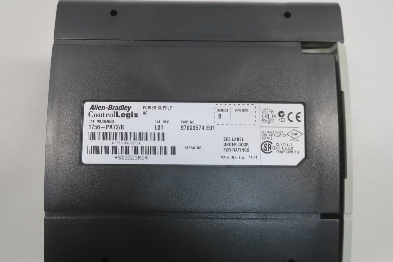
Figure 5: Rear view of the 1756-PA72 power supply, displaying the product label with model, serial, and part numbers. This label provides critical identification information.

Figure 6: The 1756-PA72 power supply in its original packaging, showing a label with product details and identifiers.
8. Warranty and Support
For warranty information and technical support, please refer to the official Allen-Bradley documentation or contact their customer service directly. Specific warranty terms may vary based on region and purchase date.


