1. Introduction
The VEMER VE618500 CM100 is a battery-powered, daily programmable wall thermostat designed for controlling heating systems. Its intuitive mechanical interface allows for easy setting of daily heating schedules and desired temperatures. This manual provides detailed instructions for the proper installation, setup, operation, and maintenance of your thermostat.
2. Safety Information
- Electrical Safety: Installation should be performed by a qualified electrician or competent person in accordance with local wiring regulations. Always disconnect power to the heating system at the main circuit breaker before beginning any wiring work.
- Battery Safety: Use only the specified battery type (2 x 1.5V AA). Do not mix old and new batteries, or different types of batteries. Dispose of used batteries responsibly.
- Placement: Install the thermostat away from direct sunlight, drafts, and heat sources (e.g., radiators, lamps) to ensure accurate temperature readings.
- Cleaning: Do not use abrasive cleaners or solvents. Clean the thermostat with a soft, damp cloth only.
3. Package Contents
Please check that all items are present in the package:
- VEMER VE618500 CM100 Wall Thermostat Unit
- Installation Kit (screws, wall plugs)
- User Manual
4. Product Overview
Familiarize yourself with the main components and controls of your thermostat.

Figure 1: Front View of the Thermostat. This image displays the front of the VEMER VE618500 CM100 thermostat, showing the large central time dial with 15-minute riders, the temperature setting dial on the right, and the mode selector switch.
4.1 Front Panel Controls
- Time Dial (Left): A 24-hour dial with 96 movable riders (pins). Each rider represents a 15-minute interval. Push riders outwards for 'ON' periods and inwards for 'OFF' periods. The current time is indicated by a pointer.
- Temperature Dial (Right): Used to set the desired room temperature, typically ranging from 5°C to 35°C.
- Mode Selector Switch: Located near the temperature dial, this switch allows you to select the operating mode.
- RESET Button: A small button, usually recessed, to reset the thermostat.

Figure 2: Side View with Mode Selector. This image shows a close-up of the side of the thermostat, highlighting the mode selector switch, which typically has positions for 'OFF', 'Programmed', and 'Continuous ON'.
4.2 Rear Panel (for Installation)

Figure 3: Rear View of the Thermostat. This image displays the back of the VEMER VE618500 CM100 thermostat, showing the mounting holes, wiring terminals (L, NO, NC), and the battery compartment cover. The model number and electrical ratings are also visible.
- Wiring Terminals: Connections for the heating system (typically Live, Normally Open, Normally Closed).
- Battery Compartment: Holds 2 x 1.5V AA batteries.
- Mounting Holes: For securing the thermostat to the wall.
5. Installation
Important: Ensure power to the heating system is disconnected before proceeding.
5.1 Mounting Location
Choose an interior wall location, approximately 1.5 meters (5 feet) from the floor, away from:
- Direct sunlight
- Drafts from windows or doors
- Heat sources (e.g., radiators, televisions, lamps)
- Areas with poor air circulation
5.2 Mounting the Thermostat
- Carefully separate the front cover from the backplate of the thermostat.
- Position the backplate on the chosen wall location and mark the drilling points.
- Drill holes and insert wall plugs (if necessary).
- Secure the backplate to the wall using the provided screws.
5.3 Wiring
Refer to the wiring diagram on the back of the thermostat (see Figure 3) and your heating system's manual for specific connections. Typically, the thermostat acts as a simple switch for your boiler. Connect the heating system's control wires to the appropriate terminals (L, NO, NC) on the thermostat's backplate.
Ensure all connections are secure and correctly insulated.
5.4 Battery Insertion
- Open the battery compartment cover on the rear of the thermostat.
- Insert two 1.5V AA alkaline batteries, observing the correct polarity (+/-).
- Close the battery compartment cover.
Once wiring and batteries are installed, reattach the front cover to the backplate. Restore power to the heating system.
6. Initial Setup
6.1 Setting the Current Time
- Gently rotate the central time dial clockwise until the current time aligns with the fixed pointer on the thermostat. The dial is a 24-hour clock.
6.2 Setting the Desired Temperature
- Rotate the temperature dial on the right to your desired room temperature. This is the temperature the thermostat will maintain during 'ON' periods.
7. Operation
7.1 Daily Programming
The VEMER VE618500 CM100 uses 96 movable riders around the time dial for daily programming. Each rider represents a 15-minute interval.
- To set an 'ON' period (heating active): Push the corresponding riders outwards.
- To set an 'OFF' period (heating inactive): Push the corresponding riders inwards.
The thermostat will activate the heating system when the current time falls within an 'ON' period (riders pushed outwards) and the room temperature is below the set temperature.
7.2 Mode Selection
Use the mode selector switch (see Figure 2) to choose the operating mode:
- Programmed Mode (Clock/Timer Symbol): The thermostat operates according to the daily program set by the riders on the time dial.
- Continuous ON Mode (Sun Symbol): The heating system will remain active continuously, attempting to maintain the set temperature, regardless of the program.
- OFF Mode (Moon Symbol / Snowflake Symbol): The heating system will remain off, regardless of the program or temperature. This is useful for extended absences or during warmer seasons.
8. Maintenance
8.1 Battery Replacement
When the batteries are low, the thermostat's performance may be affected. Replace the batteries as follows:
- Carefully remove the front cover of the thermostat.
- Open the battery compartment.
- Remove the old batteries and dispose of them properly.
- Insert two new 1.5V AA alkaline batteries, ensuring correct polarity.
- Close the battery compartment and reattach the front cover.
After battery replacement, you may need to reset the current time.
8.2 Cleaning
Clean the thermostat's exterior with a soft, dry, or slightly damp cloth. Do not use chemical cleaners, abrasives, or solvents, as these can damage the casing.
9. Troubleshooting
| Problem | Possible Cause | Solution |
|---|---|---|
| Thermostat not turning on / No display | Dead or incorrectly inserted batteries. | Check battery polarity; replace batteries. |
| Heating not activating |
|
|
| Heating runs continuously | Mode selector in 'Continuous ON' position. | Switch to 'Programmed' or 'OFF' mode. |
| Incorrect time display | Time dial not set correctly. | Adjust the time dial to the current time. |
10. Specifications
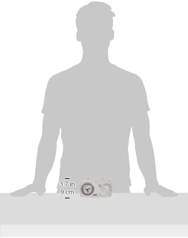
Figure 4: Thermostat Dimensions. This image provides a visual representation of the VEMER VE618500 CM100 thermostat's dimensions, indicating a width of approximately 15.6 cm (6.1 inches) and a height of 9 cm (3.5 inches).
| Feature | Detail |
|---|---|
| Model | VE618500 CM100 |
| Brand | VEMER |
| Color | White |
| Dimensions (L x W x H) | 15.6 x 3.3 x 9 cm (approx. 6.1 x 1.3 x 3.5 inches) |
| Weight | 183 g (approx. 6.4 oz) |
| Power Supply | 2 x 1.5V AA Batteries |
| Voltage | 3 Volts (battery) |
| Material | Plastic |
| Operating Mode | Heating |
| Programming | Daily, 15-minute intervals (mechanical riders) |
| Installation | Wall-mounted |
| Controller Type | Dial / Mechanical |
| Special Feature | Clock Display |
| Product Usage | HVAC Systems (Heating) |
| Temperature Control Type | Manual |
11. Warranty and Support
This VEMER product is covered by a manufacturer's warranty. For specific warranty terms and conditions, please refer to the documentation provided with your purchase or contact VEMER customer support. For technical assistance or inquiries, please visit the official VEMER website or contact their authorized service centers.


