Introduction
This manual provides comprehensive instructions for the safe installation, setup, operation, and maintenance of your new Hubbell Wiring Device-Kellems Digital Wall Switch Timer. Please read this manual thoroughly before installation and retain it for future reference.
Safety Information
WARNING: Risk of electric shock. Installation requires working with high voltage wiring. Always turn off power at the circuit breaker or fuse box before beginning installation.
- Installation should be performed by a qualified electrician or a person with knowledge of electrical wiring.
- Ensure all wiring connections are secure and comply with local electrical codes.
- Do not exceed the specified electrical ratings of the device.
- This device is intended for indoor use only.
CAUTION: Incorrect wiring can damage the device or connected equipment.
Package Contents
Verify that all components are present before installation:
- Digital Wall Switch Timer Unit
- Mounting Screws
- Wire Nuts (if included)
- Instruction Manual (this document)
Product Overview
The Hubbell Digital Wall Switch Timer is designed to provide automated control of lighting or other electrical loads. It features an LCD display for easy programming and status indication.
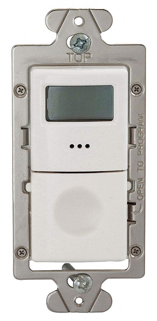
Figure 1: Front view of the Hubbell Digital Wall Switch Timer. The top section features an LCD display, and the bottom section is a hinged panel that opens to reveal programming buttons.
Key Components
- LCD Display: Shows time, program status, and settings.
- Programming Access Panel: A hinged cover that conceals the programming buttons. (Refer to Figure 1, the lower part of the white faceplate)
- Mounting Strap: Metal frame for securing the timer to an electrical box. (Refer to Figure 1, the silver metal frame)
- Wiring Terminals: Located on the rear of the unit for electrical connections. (Not visible in Figure 1, but implied)
Installation
- Turn Off Power: Locate the circuit breaker or fuse that controls the power to the switch box. Turn off the power completely. Verify power is off using a voltage tester.
- Remove Existing Switch: Carefully remove the wall plate and unscrew the existing switch from the electrical box. Disconnect the wires from the old switch.
- Identify Wires: Identify the following wires:
- Line (Hot) Wire: The wire bringing power from the circuit breaker.
- Load Wire: The wire going to the light fixture or appliance.
- Neutral Wire: (If present) Typically white.
- Ground Wire: Bare copper or green.
- Wire the Timer: Connect the wires from the electrical box to the corresponding terminals on the timer. Use wire nuts to secure connections.
- Connect the Line (Hot) wire to the timer's Line terminal.
- Connect the Load wire to the timer's Load terminal.
- Connect the Ground wire to the timer's Ground terminal.
- If a Neutral wire is present and required by the timer, connect it to the timer's Neutral terminal.
- Mount the Timer: Carefully fold the wires into the electrical box. Secure the timer to the electrical box using the provided mounting screws.
- Install Wall Plate: Attach the decorative wall plate (not included) over the timer.
- Restore Power: Turn the power back on at the circuit breaker.
Initial Setup and Programming
Setting Current Time and Day
- Open Access Panel: Gently open the hinged programming access panel on the front of the timer.
- Enter Setup Mode: Press the "SET" button (or equivalent, refer to specific button labels on your unit) to enter time setting mode.
- Adjust Time: Use the "HOUR" and "MINUTE" buttons to set the current hour and minute.
- Adjust Day: Use the "DAY" button to set the current day of the week.
- Save Settings: Press the "SET" button again or wait for the display to return to normal operation to save the settings.
Operation
Manual Override
To manually turn the connected load ON or OFF, press the main button on the front of the timer. The LCD display will indicate the current status.
Programming Schedules
The timer allows for multiple ON/OFF programs.
- Access Program Mode: Open the access panel and press the "PROG" button. The display will show "PROG 1 ON" or similar.
- Set ON Time: Use the "HOUR" and "MINUTE" buttons to set the desired ON time for Program 1.
- Set ON Days: Use the "DAY" button to select the days of the week for this ON event (e.g., Mon-Fri, Everyday, Weekend, specific days).
- Set OFF Time: Press "PROG" again to advance to "PROG 1 OFF". Set the desired OFF time and days using the "HOUR", "MINUTE", and "DAY" buttons.
- Add More Programs: Repeat steps 2-4 for additional programs (e.g., PROG 2 ON, PROG 2 OFF, etc.).
- Exit Program Mode: Press the "RUN" button (or equivalent) to exit programming and activate the schedules.
Visual and Audible Warning Option
This timer features an option for visual and audible warnings before a scheduled event. Consult the full product manual for instructions on enabling or disabling this feature, typically found within the advanced settings menu accessible via the programming buttons.
Maintenance
Cleaning
To clean the timer, wipe the surface with a soft, damp cloth. Do not use abrasive cleaners or solvents. Ensure power is off before cleaning.
Battery Replacement (if applicable)
Some digital timers include a backup battery to retain settings during power outages. If your timer's display becomes dim or settings are lost after a power interruption, the internal battery may need replacement. Refer to the specific instructions provided with your unit for battery type and replacement procedure.
Troubleshooting
| Problem | Possible Cause | Solution |
|---|---|---|
| Timer display is blank. | No power to the timer. | Check circuit breaker. Verify wiring connections. |
| Connected light/appliance does not turn ON/OFF. | Incorrect wiring; Program not set correctly; Load exceeds timer capacity. | Review wiring diagram. Re-program the timer. Ensure load (watts/amps) is within specifications. |
| Timer loses settings after power outage. | Internal backup battery (if present) is depleted. | Replace backup battery (refer to product-specific instructions). |
| Display shows erratic behavior. | Electrical interference; Internal fault. | Ensure proper grounding. If problem persists, contact customer support. |
Specifications
| Feature | Detail |
|---|---|
| Model | B076CB54FM |
| Brand | Hubbell Wiring Device-Kellems |
| Voltage | 120/277VAC |
| Watts | 960/1200 |
| Amps | 8.30 |
| Poles | 1-Pole/3-Way |
| HP @ 120V | 1/6 |
| Min. Time Setting | 5 min. |
| Max. Time Setting | 4 hr. |
| Type of Switch | Electronic |
| Color | White |
| Dimensions (L x W x D) | 4-1/2 In. x 2 In. x 3 In. (approx. 11.43cm x 5.08cm x 7.62cm) |
| Features | LCD Display, Visual and Audible Warning Option |
| Standards | UL/cUL |
| UPC | 696334092448 |
Warranty and Customer Support
For warranty information and technical assistance, please refer to the warranty card included with your product or visit the official Hubbell Wiring Device-Kellems website.
Contact Information: Please refer to the product packaging or manufacturer's website for the most current customer support contact details.