1. Product Overview
The SEINECA ABS Wheel Speed Sensor is a critical component of your vehicle's Anti-lock Braking System (ABS). It monitors the rotational speed of the wheels and transmits this data to the vehicle's Electronic Control Unit (ECU). This information is vital for the ABS to prevent wheel lock-up during braking, ensuring vehicle stability and control, especially in emergency braking situations.

Image: The SEINECA ABS Wheel Speed Sensor, showing its full length, sensor tip, and electrical connectors.
1.1 Compatibility
This ABS Wheel Speed Sensor is designed for specific Nissan models. Please verify your vehicle's make, model, and year against the table below to ensure proper fitment.

Image: Official compatibility chart for the ABS Wheel Speed Sensor.
| Brand | Model | Year |
|---|---|---|
| Nissan | Altima | 2013-2018 |
| Nissan | Maxima | 2016-2020 |
Replacement Part Numbers: 47910-3TA1A, 479103TA1A, 47910-3TA2A, 479103TA2A, ALS2554, 2ABS2759.
2. Package Contents and Visual Inspection
Upon receiving your SEINECA ABS Wheel Speed Sensor, please inspect the package contents and the sensor itself for any signs of damage or missing components.
2.1 What's Included
- 1 x ABS Wheel Speed Sensor (Front Left or Right)
2.2 Sensor Components

Image: Detail of the sensor's electrical connector, designed for secure and reliable connection to the vehicle's wiring harness.
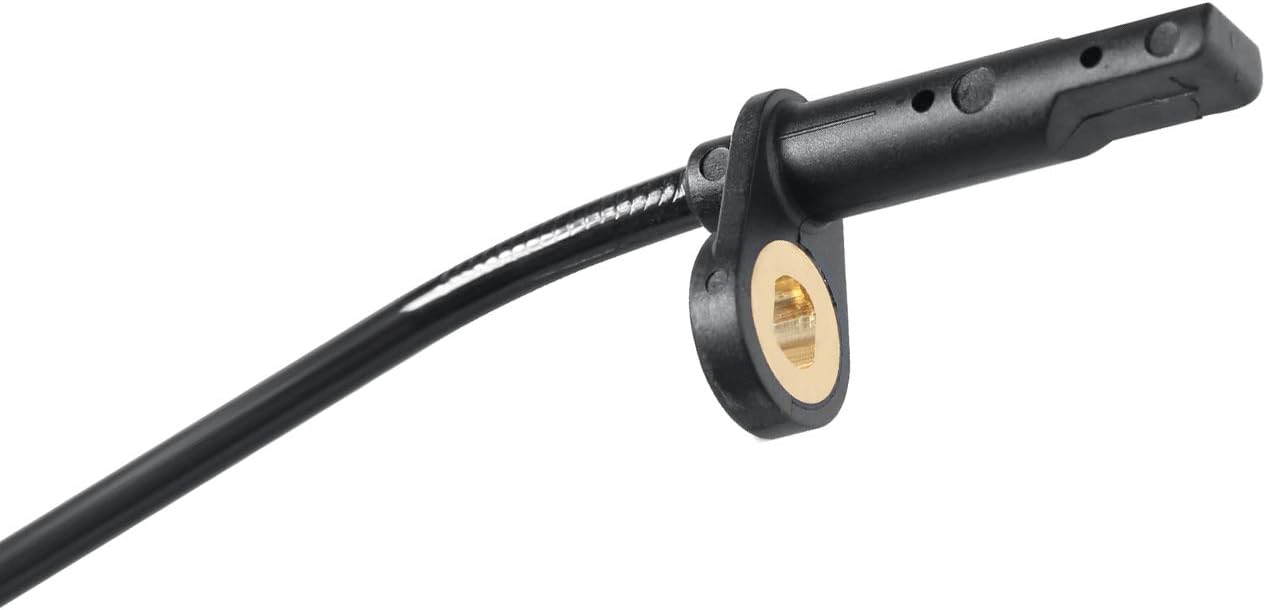
Image: The sensor tip, which reads the rotational speed from the reluctor ring on the wheel hub.

Image: The overall length of the sensor cable, approximately 39.09 inches (99.3 cm), ensuring adequate reach for installation.
2.3 Product Overview Video
Video: A detailed overview of the SEINECA ABS sensor (model 47910-3TA1A), showcasing its features and components.
3. Installation Guide
Replacing an ABS wheel speed sensor typically involves working with vehicle suspension and braking components. It is recommended that installation be performed by a qualified automotive technician. Always refer to your vehicle's specific service manual for detailed instructions and safety precautions.
3.1 General Installation Steps
- Safety First: Ensure the vehicle is safely lifted and supported on jack stands. Disconnect the negative terminal of the battery.
- Locate the Sensor: Identify the faulty ABS wheel speed sensor. It is usually mounted near the wheel hub or knuckle.
- Disconnect Electrical Connector: Carefully disconnect the electrical connector from the old sensor.
- Remove Old Sensor: Remove any retaining bolts or clips holding the sensor in place. Gently pull the old sensor out of its mounting bore.
- Clean Mounting Area: Clean the sensor mounting bore and surrounding area to ensure proper seating of the new sensor.
- Install New Sensor: Insert the new SEINECA ABS wheel speed sensor into the mounting bore. Ensure it is fully seated and secure it with the retaining bolts or clips.
- Connect Electrical Connector: Reconnect the electrical connector firmly.
- Route Cable: Route the sensor cable along the original path, securing it with any clips or ties to prevent damage from moving parts.
- Reconnect Battery: Reconnect the negative battery terminal.
- Test System: Start the vehicle and check for the ABS warning light. Drive the vehicle briefly to allow the system to self-diagnose. If the light persists, further diagnosis may be required.

Image: Illustrative diagram of an ABS wheel speed sensor's placement relative to the wheel hub and reluctor ring.

Image: An installed ABS wheel speed sensor, showing its typical mounting location on the vehicle.
4. Operating Principles
The Anti-lock Braking System (ABS) is a safety system that allows the wheels on a motor vehicle to maintain tractive contact with the road surface according to driver inputs while braking, preventing the wheels from locking up (ceasing to rotate) and avoiding uncontrolled skidding. The wheel speed sensor plays a crucial role by providing real-time data on each wheel's rotational speed to the ABS control module.

Image: Comparison of braking performance with and without ABS and Electronic Brakeforce Distribution (EBD).
5. Maintenance
ABS wheel speed sensors are generally maintenance-free. However, regular inspection during routine vehicle service can help identify potential issues early.
- Visual Inspection: Periodically check the sensor and its wiring for any signs of physical damage, corrosion, or loose connections.
- Cleanliness: Ensure the sensor tip and the reluctor ring (if visible) are free from excessive dirt, debris, or rust, which can interfere with accurate readings.
- Cable Integrity: Verify that the sensor cable is securely routed and not rubbing against any moving parts or sharp edges.

Image: Recommended lifespan for ABS sensors, typically 80,000-100,000 km or 60-90 months.
6. Troubleshooting
If you experience issues with your ABS system, such as the ABS warning light illuminating on your dashboard, the wheel speed sensor may be a contributing factor. Here are some common troubleshooting steps:
- ABS Warning Light: The most common symptom of a faulty ABS sensor is the illumination of the ABS warning light on the dashboard. This indicates a fault detected by the ABS control module.
- Loss of ABS Function: If the sensor is faulty, the ABS system may be disabled, leading to a loss of anti-lock braking capability.
- Diagnostic Trouble Codes (DTCs): Use an OBD-II scanner to retrieve diagnostic trouble codes from the vehicle's ECU. Codes related to wheel speed sensors (e.g., C0031, C0034) can pinpoint the specific sensor causing the issue.
- Wiring Inspection: Check the sensor's wiring harness for any cuts, fraying, or corrosion. Ensure the electrical connector is clean and securely attached.
- Sensor Resistance Check: A multimeter can be used to check the resistance of the sensor. Consult your vehicle's service manual for the correct resistance values.

Image: The ABS warning light on a vehicle's dashboard, indicating a system fault.
7. Technical Specifications
| Specification | Detail |
|---|---|
| Brand | SEINECA |
| Material | Acrylonitrile Butadiene Styrene |
| Mounting Type | Flange Mount |
| Output Type | Push-Pull |
| Item Weight | 1.76 ounces |
| Package Dimensions | 5.87 x 5.59 x 1.02 inches |
| Manufacturer Part Number | 47910-3TA1A, 479103TA1A, 47910-3TA2A |
| OEM Part Number | 47910-3TA1A, 47910-3TA2A, 479103TA1A, 479103TA2A |
8. Warranty and Support
SEINECA stands behind the quality of its products.
- Warranty: This product comes with a 1-Year Quality Warranty.
- Satisfaction Guarantee: We offer a 100% Satisfaction Guarantee.
- Customer Service: Our dedicated customer service team is available 24-hour online to assist with any issues or questions you may have. Please contact us for support to ensure a satisfying shopping and after-sales experience.