1. Introduction
This manual provides essential information for the safe and effective use of your DROK Mini DC-DC Buck Converter module. Please read these instructions thoroughly before installation and operation to ensure optimal performance and prevent damage.
2. Safety Information
- Ensure the input voltage does not exceed the specified maximum of 24V DC.
- Observe correct polarity when connecting input and output wires. Incorrect connections can damage the module and connected devices.
- Do not exceed the maximum output current of 3A. For continuous operation at or near 3A, additional cooling may be required to prevent overheating.
- Handle the module with care to avoid electrostatic discharge, which can damage sensitive electronic components.
- Keep the module away from moisture and extreme temperatures.
3. Product Overview
The DROK Mini DC-DC Buck Converter is a compact voltage reducer designed to step down a DC input voltage to a lower, stable DC output voltage. It features both adjustable and fixed output voltage options, making it versatile for various electronic projects.
Component Identification
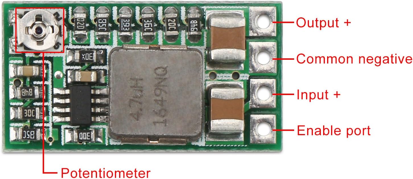
- Output +: Positive terminal for the regulated output voltage.
- Common negative: Ground connection for both input and output.
- Input +: Positive terminal for the input DC voltage (4.5V to 24V).
- Enable port (EN): Controls the module's operation. Defaults to working mode. Connecting to a low electrical level (e.g., ground) will turn the module off.
- Potentiometer: Used to adjust the output voltage when in adjustable mode.
4. Specifications
| Feature | Value |
|---|---|
| Input Voltage Range | DC 4.5V - 24V |
| Adjustable Output Voltage Range | 0.8V - 17V |
| Fixed Output Voltage Options | 1.8V, 2.5V, 3.3V, 5V, 9V, 12V |
| Maximum Output Current | 3A (with enhanced cooling) |
| Typical Output Current (without extra cooling) | 1.5A (e.g., 12V input, 1.5A output) |
| Efficiency | High efficiency (specific value varies with load) |
| Dimensions | Approx. 20.5mm x 11mm (smaller than half a one-dollar coin) |
| Model Number | 2001708006 |
5. Setup and Configuration
5.1. Wiring Connections
Connect your input power source to the Input + and Common negative (GND) terminals. Connect your load to the Output + and Common negative (GND) terminals. Ensure all connections are secure and observe correct polarity.
5.2. Output Voltage Adjustment
The module offers two methods for setting the output voltage:
Adjustable Output Voltage:
By default, the module is in adjustable mode. Use a small screwdriver to turn the potentiometer (refer to Image 1) to set the desired output voltage between 0.8V and 17V. It is recommended to monitor the output voltage with a multimeter during adjustment.
Fixed Output Voltage:
To use a fixed output voltage (1.8V, 2.5V, 3.3V, 5V, 9V, 12V), you must modify the module by soldering. This involves cutting a specific trace and then soldering a jumper to the desired voltage pad on the back of the board.

- Locate the 'ADJ' pad on the back of the module.
- Carefully cut the trace connecting the 'ADJ' pad to the rest of the circuit (as indicated in Image 2).
- Solder a jumper wire or bridge the solder pad corresponding to your desired fixed voltage (e.g., 5V, 3.3V) to the adjacent common pad.
5.3. Enable Port (EN) Usage
The integrated Enable port (EN) defaults to working mode. To turn the module off, connect the EN pin to a low electrical level (e.g., ground). This feature provides convenient control over the module's power state.
6. Operating Instructions
Once properly wired and configured, apply the DC input voltage. The module will convert it to the set output voltage. Always ensure your load's current draw does not exceed the module's capacity, especially without additional cooling.
Demonstration Video
7. Maintenance
The DROK Mini DC-DC Buck Converter is designed for reliable operation and requires minimal maintenance. Keep the module clean and free from dust and debris. Periodically check connections for tightness and ensure no wires are frayed or damaged. Avoid exposing the module to harsh chemicals or solvents.
8. Troubleshooting
- No Output Voltage:
- Check input voltage and polarity.
- Ensure the Enable (EN) pin is not connected to a low electrical level, which would turn the module off.
- Verify all connections are secure.
- Incorrect Output Voltage:
- If in adjustable mode, use a multimeter to accurately set the voltage with the potentiometer.
- If in fixed mode, ensure the correct trace was cut and the desired voltage pad was properly soldered.
- Module Overheating:
- Reduce the load current. The module is rated for 3A maximum, but requires enhanced cooling at full load. For typical use without additional cooling, keep current below 1.5A.
- Ensure adequate airflow around the module.
- Unstable Output:
- Check for loose connections or faulty wiring.
- Ensure the input power source is stable.
9. Warranty and Support
Each product purchased from DROK includes a one-year service period. In the event of any quality issues with your item, you are eligible for a brand new replacement. For support or warranty claims, please contact DROK customer service through the retailer where the product was purchased.


