Introduction
This manual provides essential information for the installation, operation, maintenance, and troubleshooting of the Allen-Bradley 1756-OW16I ControlLogix Relay Output Module. This module is designed for industrial control systems, providing reliable relay output capabilities within a ControlLogix chassis.
Setup
Unpacking and Inspection
Carefully remove the module from its packaging. Inspect the module for any signs of physical damage during transit. Do not install a damaged module. Ensure all components are present as per the packing list.
Mounting
The 1756-OW16I module is designed for DIN Rail Mount installation within a ControlLogix chassis. Ensure the chassis is powered off before inserting or removing modules.
- Align the module with an available slot in the ControlLogix chassis.
- Gently push the module into the slot until it clicks securely into place. Ensure the module is fully seated to establish proper electrical connections.
- Secure the module using any retaining clips or screws provided by the chassis.

Wiring
The module utilizes screw-type connectors for relay output wiring. Refer to the system's wiring diagrams and local electrical codes for proper connection procedures. Ensure all connections are secure to prevent intermittent operation or damage.

Operating
Functionality
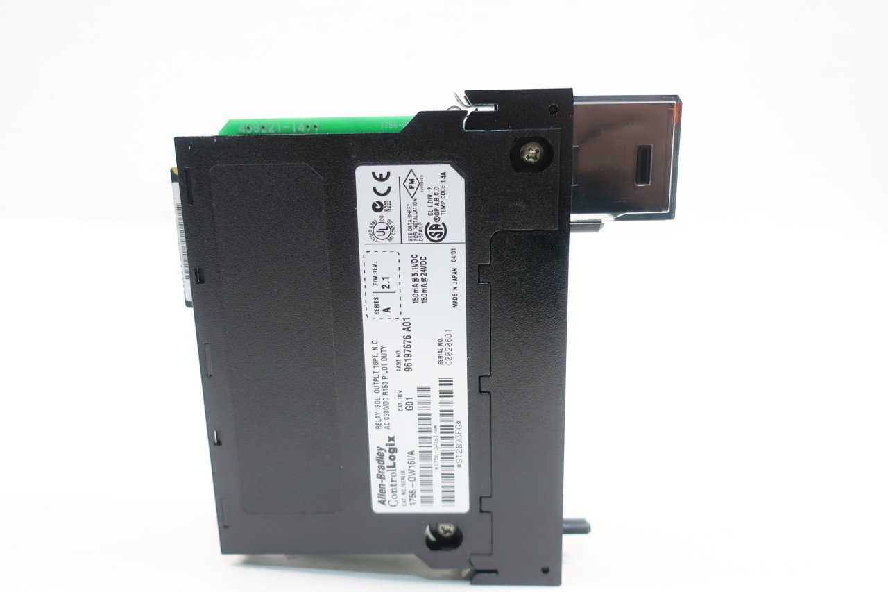
The 1756-OW16I is a 16-point isolated relay output module. It provides discrete output control for various industrial applications. The module receives commands from the ControlLogix processor and activates its internal relays to control external devices.
Indicators
The module features status indicators (e.g., 'ST' for status) on its front panel. These indicators provide visual feedback on the module's operational status and the state of individual output channels. Consult the ControlLogix system documentation for a detailed explanation of indicator states.
Maintenance
General Care
To ensure optimal performance and longevity of the module, follow these general maintenance guidelines:
- Keep the module and surrounding area clean and free from dust, dirt, and moisture.
- Ensure proper ventilation around the ControlLogix chassis to prevent overheating.
- Periodically check all wiring connections for tightness and integrity.
Inspection
Regularly inspect the module for any signs of wear, corrosion, or damage. Pay close attention to the connectors and the module's housing. If any damage is observed, replace the module immediately.
Troubleshooting
This section provides basic troubleshooting steps for common issues. For more complex problems, refer to the comprehensive ControlLogix system documentation or contact technical support.
| Symptom | Possible Cause | Solution |
|---|---|---|
| Module status indicator (ST) is off or red. | No power to module, module not seated correctly, module fault. | Verify chassis power. Re-seat the module. Check ControlLogix controller diagnostics for fault codes. |
| Output relay not activating. | Incorrect programming, wiring error, external device fault, faulty relay. | Verify PLC logic. Check wiring to the external device. Test the external device. Consider replacing the module if other checks fail. |
| Intermittent output operation. | Loose wiring connection, electrical noise, module overheating. | Check and tighten all wiring connections. Ensure proper grounding and shielding. Verify adequate ventilation. |
Specifications
The following table outlines the key technical specifications for the Allen-Bradley 1756-OW16I ControlLogix Relay Output Module.
| Attribute | Value |
|---|---|
| Model Number | 1756-OW16I |
| Series | A |
| Product Dimensions | 6 x 6 x 2 inches; 14.4 ounces |
| Manufacturer | ALLEN BRADLEY |
| Connector Type | Screw |
| Contact Material | Silver |
| Contact Type | Normally Open |
| Mounting Type | DIN Rail Mount |
Warranty and Support
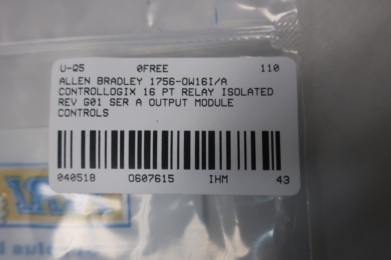
For warranty information and technical support, please refer to the official Allen-Bradley documentation or contact your authorized distributor. When seeking support, it is helpful to have the module's serial number and part number readily available.
Relevant codes for documentation or support: ST2BQ3FG and 607615.


