1. Introduction
This manual provides comprehensive instructions for the installation, operation, and maintenance of your Commax TP-12RM Master Interphone System. This system facilitates communication between a central master unit and up to twelve remote units. Please read this manual thoroughly before operating the system to ensure proper function and safety.
2. Safety Information
- Ensure all wiring is performed by a qualified professional to prevent electrical hazards.
- Use only the provided RF-24015S DC24V power supply. Using an incorrect power supply may damage the units and void the warranty.
- Do not expose the units to water, excessive moisture, or extreme temperatures.
- Do not attempt to open or repair the units yourself. Refer all servicing to authorized personnel.
- Keep the units away from strong electromagnetic fields.
3. Package Contents
Verify that all components are present in the package:
- 1 x Commax TP-12RM Master Unit
- 12 x Commax TP-S Remote Units
- 1 x Commax RF-24015S DC24V Power Supply

Figure 1: Overview of the Commax TP-12RM Master Interphone System components. This image displays the TP-12RM master unit on the left, twelve TP-S remote units arranged in two rows on the right, and the RF-24015S power supply at the bottom left. All units are white and feature a classic interphone design with coiled handsets.
4. Setup and Installation
4.1 Wiring Diagram
The Commax TP-12RM system requires a 2-wire connection for each remote unit to the master unit. The power supply connects directly to the master unit. Ensure proper polarity during wiring.

Figure 2: System Wiring Diagram for the Commax TP-12RM. This diagram illustrates the connection of the TP-12RM master unit (represented by a central circuit board with terminals) to multiple TP-S remote units (shown as handsets). Each TP-S unit connects to the master unit via two wires. The DC24V power supply is shown connected to the master unit, providing power to the entire system.
4.2 Installation Steps
- Mounting: The master unit (TP-12RM) can be wall or desktop surface mounted. The remote units (TP-S) are surface mounted. Choose appropriate locations for optimal communication and accessibility.
- Wiring: Connect each TP-S remote unit to the TP-12RM master unit using a 2-wire cable. Ensure secure connections at all terminals. The maximum transmission distance is up to 1000 meters (3000 feet) with Ø0.65mm wire.
- Power Supply Connection: Connect the RF-24015S DC24V power supply to the designated power input terminals on the TP-12RM master unit.
- Power On: Plug the power supply into a standard AC outlet (AC100V-240V, 50/60Hz). The system will power on.
5. Operating Instructions
5.1 Making a Call (Master to Remote)
- Lift the handset on the TP-12RM master unit.
- Press the button corresponding to the desired remote unit (1-12).
- An electric call tone will sound at the remote unit.
- When the remote unit lifts its handset, communication can begin.
5.2 Making a Call (Remote to Master)
- Lift the handset on the TP-S remote unit.
- A melody sound will be heard at the TP-12RM master unit.
- The LED indicator on the master unit corresponding to the calling remote unit will illuminate.
- The master unit operator lifts the handset to establish communication.
5.3 Communication
Once a call is established, speak clearly into the handset. The system supports two-way communication between the master unit and one remote unit at a time. Remote units cannot communicate directly with each other.
6. Maintenance
- Cleaning: Wipe the units with a soft, dry cloth. Do not use abrasive cleaners or solvents.
- Inspection: Periodically check all wiring connections for security and signs of wear.
- Environment: Ensure the units are kept in a clean, dry environment within the specified operating temperature range (0°C ~ 40°C / 32°F ~ 104°F).
7. Troubleshooting
If you encounter issues with your Commax interphone system, refer to the following common problems and solutions:
- No Power:
- Check if the power supply is securely plugged into a working outlet.
- Verify the power supply connection to the master unit.
- No Communication:
- Ensure all wiring connections between the master and remote units are secure and correctly polarized.
- Check if the correct remote unit button is pressed on the master unit.
- Confirm both handsets are lifted during a call.
- Poor Audio Quality:
- Inspect wiring for damage or loose connections.
- Ensure the transmission distance does not exceed 1000 meters with the recommended wire gauge.
- Remote Unit Not Ringing:
- Verify the wiring to that specific remote unit.
- Ensure the master unit is powered on and functioning.
If problems persist, contact customer support for assistance.
8. Specifications
Detailed specifications for the Commax TP-12RM Master Unit, TP-S Remote Unit, and RF-24015S Power Supply are provided below:
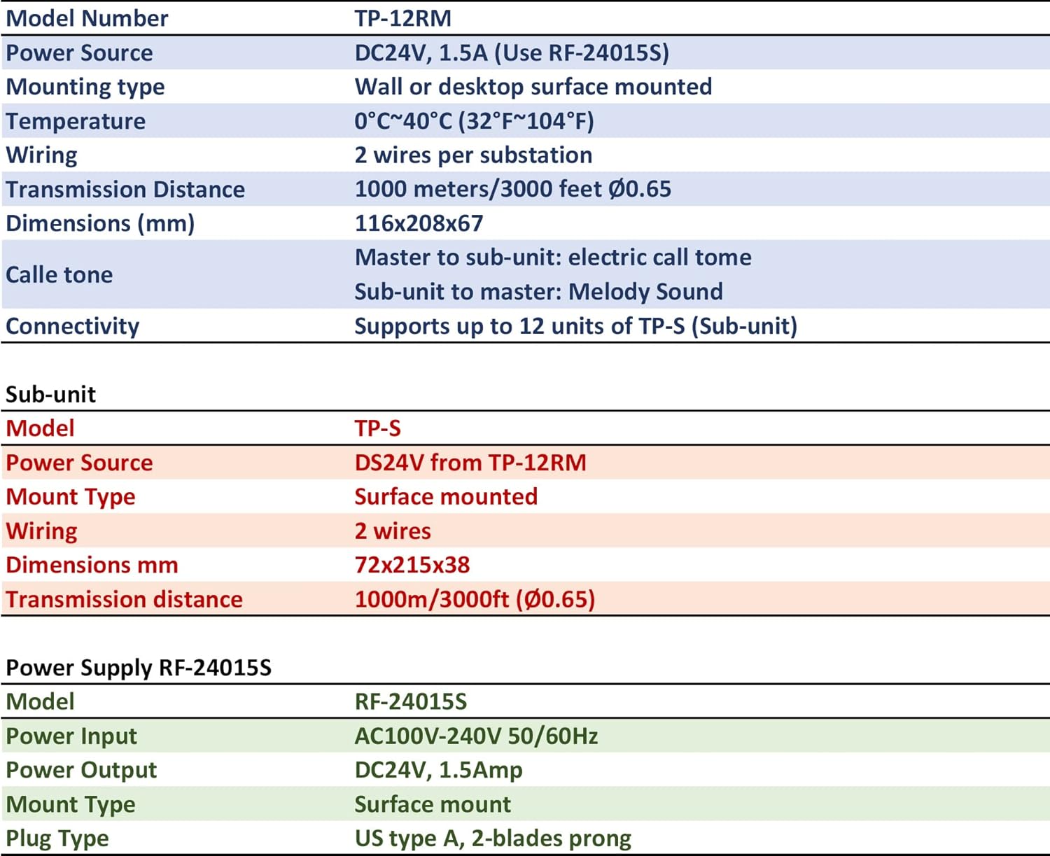
Figure 3: Detailed specifications for the Commax TP-12RM Master Unit, TP-S Remote Unit, and RF-24015S Power Supply. This image presents a table format outlining key technical details such as model numbers, power sources, mounting types, wiring requirements, operating temperatures, dimensions, transmission distances, and call tone types for each component of the interphone system.
| Feature | TP-12RM (Master Unit) | TP-S (Remote Unit) | RF-24015S (Power Supply) |
|---|---|---|---|
| Model Number | TP-12RM | TP-S | RF-24015S |
| Power Source | DC24V, 1.5A (from RF-24015S) | DC24V (from TP-12RM) | AC100V-240V 50/60Hz Input, DC24V 1.5Amp Output |
| Mounting Type | Wall or Desktop Surface Mounted | Surface Mounted | Surface Mount |
| Operating Temperature | 0°C ~ 40°C (32°F ~ 104°F) | ||
| Wiring | 2 wires per substation | N/A | |
| Transmission Distance | Up to 1000 meters / 3000 feet (Ø0.65mm wire) | N/A | |
| Dimensions (mm) | 116 x 208 x 67 | 72 x 215 x 38 | N/A |
| Call Tone | Electric call tone (to sub-unit), Melody sound (from sub-unit) | Electric call tone (from master), Melody sound (to master) | N/A |
| Connectivity | Supports up to 12 units of TP-S (Sub-unit) | Connects to TP-12RM Master Unit | N/A |
| Plug Type | N/A | N/A | US Type A, 2-blades prong |
9. Warranty and Support
Commax products are designed for reliability and performance. For warranty information, please refer to the warranty card included with your purchase or contact your authorized Commax dealer. For technical support or service inquiries, please contact Commax customer service through their official website or the contact information provided at the point of purchase.