
1. Introduction
The Godox SK400II is a professional studio flash strobe light designed for various photography applications, including e-commerce product photography, portraiture, and lifestyle shoots. It features a built-in Godox 2.4G wireless X system for convenient control and offers precise power output adjustments. This manual will guide you through the components, setup, operation, and maintenance of your SK400II unit.
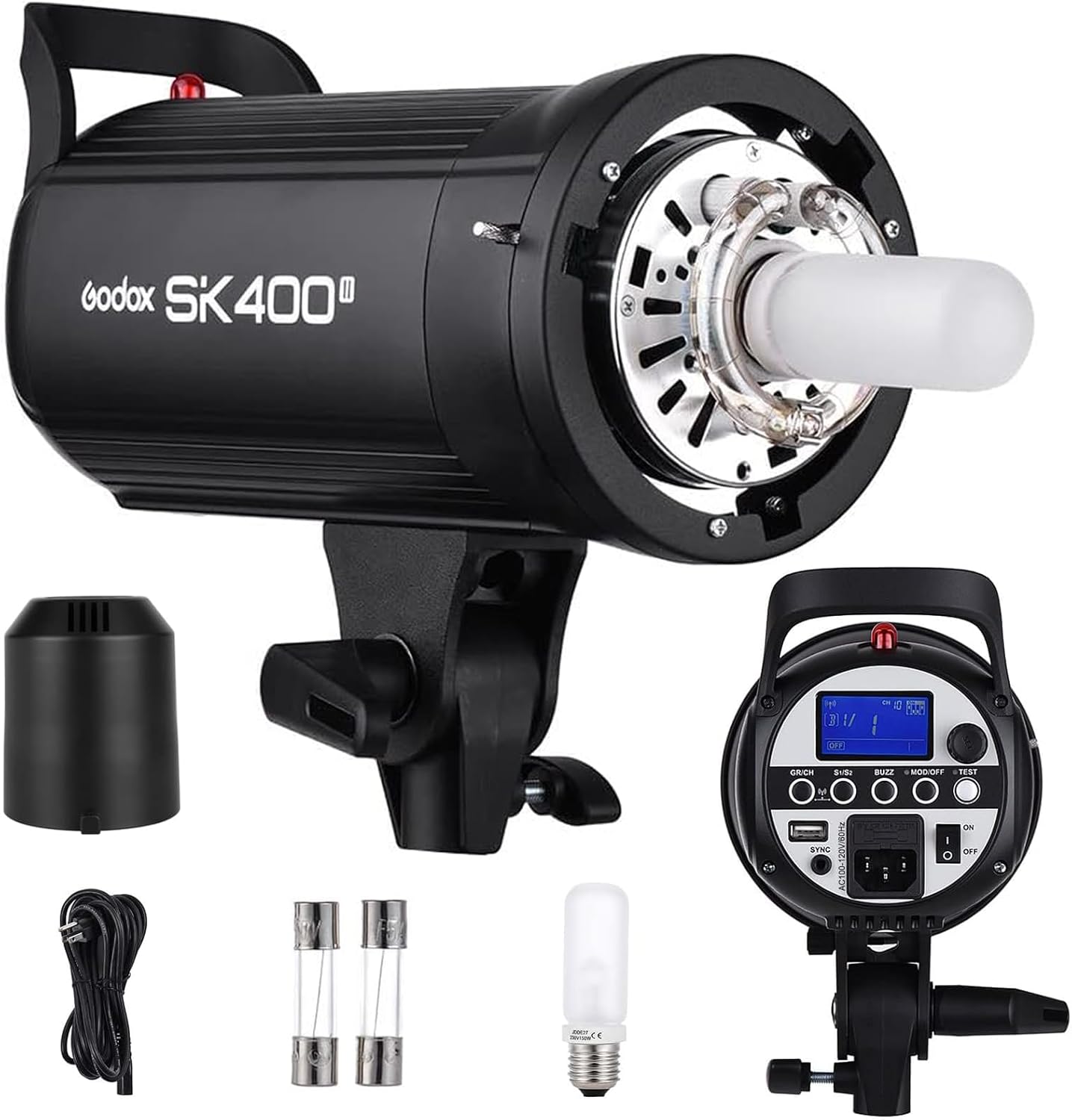
Image 1.1: The Godox SK400II studio flash unit with its main components and accessories.
2. Product Features
- Integrated Godox 2.4G Wireless X System: Enables wireless control of flash power, modeling lamp, and buzzer functions with compatible triggers (e.g., X1, XT16, FT-16).
- High Power Output: Offers a maximum power of 400Ws with a Guide Number (GN) of 65.
- Color Temperature: Consistent color temperature of 5600K.
- Precise Power Adjustment: Output displayed on an LCD panel, adjustable in 40 steps from 1/16 to 1/1 (or 6.0 to 10.0).
- Adjustable Modeling Lamp: A 150W modeling lamp with adjustable power levels from 5% to 100%.
- Bowens Mount: Compatible with a wide range of studio light modifiers and accessories.
- Advanced Flash Tube: Utilizes a Germany Heimann flash tube for high intensity and accurate color temperature.
- Built-in Cooling Fan: Features an integrated radiator to protect the flash tube and extend service life.
- Intuitive Control Panel: Equipped with a clear LCD panel and new touch-sensitive buttons for easier control.

Image 2.1: The SK400II features a Bowens mount for versatility and a new button design for enhanced usability.
3. Package Contents
Upon unpacking, please verify that all the following items are included in your package:
- Godox SK400II Studio Flash Unit
- Power Cable
- Modeling Lamp
- Fuse (spare)
- Lamp Cover
- Instruction Manual

Image 3.1: All items included in the Godox SK400II product package.
4. Component Identification
Familiarize yourself with the various parts and controls of your Godox SK400II flash unit:

Image 4.1: Detailed diagram showing the front and rear components of the SK400II flash unit.
- Bowens Mount: For attaching light modifiers.
- Modeling Lamp: Provides continuous light for previewing lighting effects.
- Flash Tube: The main flash light source.
- Umbrella Hole: For mounting photographic umbrellas.
- Light Sensor: Detects pre-flashes for S1/S2 slave modes.
- BUZZ Button: Toggles the audible flash ready indicator.
- S1/S2 Slave Model Button: Selects slave triggering modes.
- Group/Channel Button (GR/CH): Adjusts wireless groups and channels.
- Wireless Control Port: For connecting external wireless receivers.
- Sync Cord Jack: For wired synchronization with a camera.
- AC Power Socket: Connects the power cable.
- Fuse Compartment: Houses the protective fuse.
- Power Switch: Turns the unit on or off.
- Test Button: Fires a test flash.
- MOD/OFF Modeling Lamp Button: Controls the modeling lamp.
- Select Dial + Set Button: Navigates menus and confirms settings on the LCD panel.
- LCD Panel: Displays current settings and flash status.
5. Setup
5.1 Mounting the Flash Unit
The SK400II features a standard light stand mount. Securely attach the flash unit to a sturdy light stand. Adjust the tilting angle as needed for your lighting setup. Ensure the locking knob is tightened to prevent accidental movement.

Image 5.1: The flash unit's adjustable angle mechanism for precise light positioning.
5.2 Connecting Power
Connect the provided power cable to the AC power socket on the rear of the flash unit and then plug it into a suitable power outlet (AC100-120V/60Hz). Ensure the power switch is in the "OFF" position before connecting.
5.3 Attaching Light Modifiers
The SK400II is equipped with a Bowens mount. To attach a light modifier (e.g., softbox, reflector), align the modifier's mount with the flash unit's Bowens mount, insert, and twist clockwise until it locks into place. To remove, press the release button and twist counter-clockwise.
6. Operation
6.1 Power On/Off
Flip the power switch located on the rear panel to the "ON" position to power on the flash unit. The LCD panel will illuminate. To power off, flip the switch to "OFF".
6.2 Adjusting Flash Power Output
Use the Select Dial on the rear panel to adjust the flash power output. The power can be set from 1/16 to 1/1 (or 6.0 to 10.0) in 40 precise steps. The current setting is displayed on the LCD panel.

Image 6.1: The clear LCD panel displays precise output settings, adjustable from 1/16 to 1/1.
6.3 Modeling Lamp Control
Press the MOD/OFF button to cycle through modeling lamp modes: ON, OFF, and Proportional. The modeling lamp's brightness can be adjusted from 5% to 100% using the Select Dial when the lamp is on.

Image 6.2: Demonstrates the adjustable brightness of the 150W modeling lamp.
6.4 Godox 2.4G Wireless X System
The SK400II features an integrated 2.4G wireless X system for remote control. This system supports 16 groups (0-9, A-F) and 32 channels (1-32).
- Setting Group and Channel: Press the GR/CH button to select the group or channel, then use the Select Dial to change the value. Press SET to confirm.
- Wireless Triggering: Use a compatible Godox 2.4G wireless trigger (e.g., X1, XT16, FT-16, sold separately) to remotely adjust flash power, control the modeling lamp, and trigger the flash. Ensure the trigger and flash are set to the same group and channel.

Image 6.3: The built-in Godox 2.4G Wireless X-System allows for remote control of the flash unit.
6.5 Slave Modes (S1/S2)
The SK400II offers two optical slave modes, activated by pressing the S1/S2 button:
- S1 Mode: The flash will fire in response to a single flash from another flash unit. This is suitable for manual flash units without pre-flash functions.
- S2 Mode: The flash will ignore the first pre-flash from a TTL flash unit and fire on the second flash. This is suitable for cameras with red-eye reduction or other pre-flash functions.

Image 6.4: The light sensor enables S1 and S2 slave modes for optical triggering.
6.6 Test Button
Press the TEST button to fire a test flash. This is useful for checking lighting setups and ensuring the flash is functioning correctly.
6.7 Buzzer Function
Press the BUZZ button to toggle the audible beep that indicates when the flash is fully recycled and ready to fire again.
7. Maintenance
- Cleaning: Use a soft, dry cloth to clean the exterior of the flash unit. For the flash tube and modeling lamp, use a clean, lint-free cloth. Avoid using harsh chemicals or abrasive materials.
- Storage: Store the flash unit in a cool, dry place, away from direct sunlight and excessive humidity. Ensure the lamp cover is in place to protect the flash tube and modeling lamp.
- Fuse Replacement: If the unit fails to power on, check the fuse in the fuse compartment. Replace it with a fuse of the same type and rating (refer to specifications for details). Always disconnect power before replacing the fuse.
- Flash Tube Replacement: The flash tube is a user-replaceable part. Consult a qualified technician or the manufacturer's support for guidance on replacement to avoid damage.
8. Troubleshooting
| Problem | Possible Cause | Solution |
|---|---|---|
| Flash unit does not power on. | Power cable not connected; Power switch off; Blown fuse. | Ensure power cable is securely connected; Turn power switch to ON; Replace fuse with correct rating. |
| Flash does not fire. | Not fully recycled; Trigger not connected/paired; Incorrect slave mode; Flash tube faulty. | Wait for recycle beep/indicator; Check trigger connection/settings (group/channel); Select appropriate S1/S2 mode; Contact service for flash tube replacement. |
| Modeling lamp not working. | Lamp off; Lamp faulty. | Press MOD/OFF button to turn on; Replace modeling lamp. |
| Inconsistent flash output. | Low power setting; Unit not fully recycled; Overheating. | Increase power setting; Allow sufficient recycle time; Allow unit to cool down. |
| Wireless control not working. | Incorrect group/channel; Trigger not compatible; Distance too far. | Ensure flash and trigger are on same group/channel; Use compatible Godox 2.4G X system trigger; Reduce distance between trigger and flash. |
9. Technical Specifications
| Feature | Specification |
|---|---|
| Model | SK400II |
| Max Power | 400Ws |
| Guide Number (GN) | 65 (m ISO 100) |
| Color Temperature | 5600K ± 200K |
| Power Output Control | 40 steps (1/16-1/1 or 6.0-10.0) |
| Modeling Lamp | 150W, adjustable 5%-100% |
| Recycle Time | 0.1-1.0s (at full power) |
| Flash Duration | 1/2000s - 1/800s |
| Sync Mode | Sync cord, Test button, Slave triggering, Wireless control port |
| Wireless Control | Godox 2.4G Wireless X System (16 groups, 32 channels) |
| Operating Voltage | AC100-120V/60Hz |
| Dimensions (with lamp cover) | 45 x 28 x 22 cm (approx.) |
| Weight | 3.52 kg (approx.) |
| Mounting Type | Bowens Mount |
10. Safety Precautions
- Do not disassemble or modify the unit. High voltage components are present.
- Keep the unit dry. Do not operate with wet hands or in rain/damp conditions.
- Ensure proper ventilation to prevent overheating. Do not block cooling vents.
- Avoid direct eye exposure to the flash.
- Always disconnect power before performing any maintenance or changing accessories.
- Use only the specified power voltage.
11. Warranty and Support
For warranty information and technical support, please refer to the warranty card included with your product or visit the official Godox website. Keep your purchase receipt as proof of purchase for warranty claims.