
1. Introduction
The STEPPERONLINE DM556T is a fully digital stepper drive developed with advanced DSP control algorithms. It is designed to drive 2-phase and 4-phase hybrid stepper motors, specifically Nema 23 and Nema 24 motors. This manual provides detailed instructions for the proper installation, configuration, and operation of the DM556T stepper driver, ensuring optimal performance and longevity.

Figure 1: Front view of the STEPPERONLINE DM556T Digital Stepper Driver, showing terminal blocks and DIP switches.
2. Features
- High-quality construction for reliable performance.
- Manufactured by Leadshine, ensuring professional-grade performance.
- Compatible with Nema 23 and Nema 24 stepper motors.
- Anti-Resonance provides optimal torque and nulls mid-range instability.
- Motor Auto-identification and parameter Auto-configuration technology, offers optimal responses with different motors.
- Multi-Stepping allows a low resolution step input to produce a higher microstep output for smooth motor performance.
- Soft-start with no 'jump' when power on.
- Input voltage 20-50VDC.
- Output current 1.8-5.6A.
- Pulse input frequency up to 200 KHz.
- TTL compatible and optically isolated input.
- Automatic idle-current reduction.
- Supports PUL/DIR and CW/CCW modes.
- Over-voltage, over-current, phase-error protection.
3. Specifications
3.1 Electrical Specifications

Figure 2: Electrical specifications for the DM556T driver, including output current, supply voltage, logic signal current, pulse input frequency, and minimal pulse width.
3.2 Operating Environment and Other Specifications
| Category | Parameter | Value |
|---|---|---|
| Cooling | Natural Cooling or Forced Cooling | |
| Environment | Avoid dust, oil fog, and corrosive gases | |
| Ambient Temperature | 0°C – 65°C | |
| Operating Humidity | 40%RH–90%RH | |
| Operating Temperature | 0°C - 50°C (32°F - 122°F) | |
| Vibration | 10 - 50Hz / 0.15mm | |
| Storage Temperature | -20°C - 65°C (-4°F - 149°F) | |
| Weight | Approx. 300g (10.6oz) | |
| Product Dimensions | 1.33 x 1.33 x 2.97 inches (33.8 x 33.8 x 75.4 mm) | |
| Item Model Number | DM556T | |
| Manufacturer | Leadshine Technology Co., Ltd. | |
3.3 Mechanical Specifications
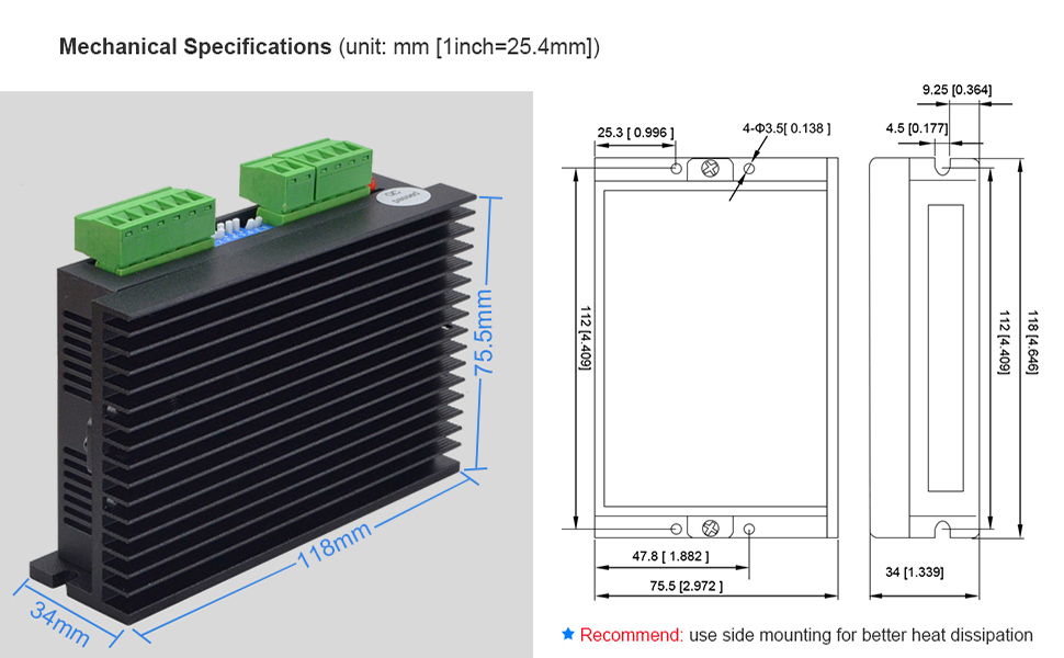
Figure 3: Mechanical dimensions of the DM556T driver. Side mounting is recommended for better heat dissipation.
4. Setup and Installation
4.1 Wiring Connections
The DM556T driver features clearly labeled terminal blocks for power, motor, and control signals. Ensure all connections are secure and correctly polarized to prevent damage to the driver or motor.
- Power Supply (+Vdc, GND): Connect a DC power supply within the 20-50VDC range. Observe polarity.
- Motor Connections (A+, A-, B+, B-): Connect the stepper motor phases to these terminals. For 2-phase motors, ensure correct phase matching.
- Control Signals (PUL+, PUL-, DIR+, DIR-, ENA+, ENA-): These are optically isolated inputs for Pulse, Direction, and Enable signals.
- Alarm Output (ALM+, ALM-): Provides an alarm signal in case of protection activation.

Figure 4: Angled view of the DM556T driver, highlighting the terminal blocks for power, motor, and control signals.
4.2 Control Signal Voltage Selection
The DM556T driver has a selector for control signal voltage. The factory setting is typically 24V. If using a 5V control signal (e.g., from a microcontroller), ensure the selector is set to 5V. If using 24V (e.g., from a PLC) with a driver configured for 5V, external 2KΩ resistors may be required.

Figure 5: Comparison table showing differences between DM556T(V4.0) and DM556T, including control signal voltage selection and digital output.
4.3 Mounting
Mount the DM556T driver in a location that allows for adequate heat dissipation. Side mounting is recommended to maximize cooling efficiency, especially in applications requiring continuous operation or high current settings. Ensure sufficient airflow around the heatsink fins.
5. Operating Instructions
The DM556T driver features an 8-bit DIP switch for configuring dynamic current, microstep resolution, and standstill current. Switches 1-3 control dynamic current, switch 4 controls standstill current, and switches 5-8 control microstep resolution.

Figure 6: Diagram illustrating the function of each DIP switch for dynamic current, standstill current, and microstep resolution settings.
5.1 Current Setting (SW1, SW2, SW3)
Use DIP switches SW1, SW2, and SW3 to set the peak output current for the motor. Refer to the table below for specific current values based on switch positions. 'ON' typically corresponds to a lower value, and 'OFF' to a higher value, but always consult the table on the driver or in the diagram.
| Peak Current (A) | RMS Current (A) | SW1 | SW2 | SW3 |
|---|---|---|---|---|
| 1.8 | 1.3 | off | off | off |
| 2.1 | 1.5 | on | off | off |
| 2.7 | 1.9 | off | on | off |
| 3.2 | 2.3 | on | on | off |
| 3.8 | 2.7 | off | off | on |
| 4.3 | 3.1 | on | off | on |
| 4.9 | 3.5 | off | on | on |
| 5.6 | 4.0 | on | on | on |
5.2 Microstep Resolution Setting (SW5, SW6, SW7, SW8)
Use DIP switches SW5, SW6, SW7, and SW8 to set the desired microstep resolution (pulses per revolution). This determines the smoothness of motor movement. Refer to the table below for specific settings.
| Pulse/Rev | SW5 | SW6 | SW7 | SW8 |
|---|---|---|---|---|
| 200 | on | on | on | on |
| 400 | off | on | on | on |
| 800 | on | off | on | on |
| 1600 | off | off | on | on |
| 3200 | on | on | off | on |
| 6400 | off | on | off | on |
| 12800 | on | off | off | on |
| 25600 | off | off | off | on |
| 1000 | on | on | on | off |
| 2000 | off | on | on | off |
| 4000 | on | off | on | off |
| 5000 | off | off | on | off |
| 8000 | on | on | off | off |
| 10000 | off | on | off | off |
| 20000 | on | off | off | off |
| 25000 | off | off | off | off |
5.3 Standstill Current (SW4)
DIP switch SW4 controls the standstill current reduction. When SW4 is 'ON', the driver operates in half-current mode when the motor is idle. When 'OFF', it operates in full-current mode. Half-current mode reduces motor heating and power consumption during periods of inactivity.

Figure 7: Top view of the DM556T driver, clearly showing the 8-bit DIP switch for configuration.
6. Protection Functions
The DM556T driver incorporates several built-in protection features to enhance reliability and prevent damage to the driver and connected components. These protections are indicated by the red LED blinking in specific sequences.

Figure 8: Table detailing the protection functions, corresponding red LED blink sequences, and their descriptions.
- Over-current Protection: Activated when the peak current exceeds the limit. The red LED blinks once.
- Over-voltage Protection: Activated when the drive working voltage is greater than 60VDC. The red LED blinks twice.
- Reserved: A third blink sequence is reserved for future protection features.
When any of these protections are active, the motor shaft will be free, and the red LED will blink. To reset the drive, remove the cause of the problem and then cycle the power to the unit.
7. Troubleshooting
This section provides guidance for diagnosing and resolving common issues encountered with the DM556T stepper driver.

Figure 9: Troubleshooting guide listing common symptoms and their possible causes.
| Symptoms | Possible Problems |
|---|---|
| Motor is not rotating | No power |
| Fault condition exists | |
| Motor rotates in the wrong direction | Motor phases may be connected in reverse |
| The drive is in fault | DIP switch current setting is wrong |
| Something wrong with motor coil | |
| Erratic motor motion | Control signal is too weak |
| Control signal is interfered | |
| Wrong motor connection | |
| Motor stalls during acceleration | Current setting is too small, losing steps |
| Acceleration is set too high | |
| Excessive motor and drive heating | Power supply voltage too low |
| Inadequate heat sinking / cooling | |
| Current is set too high |
8. Maintenance
The DM556T stepper driver is designed for long-term reliability with minimal maintenance. However, adhering to the following guidelines can help ensure its continued optimal performance:
- Environmental Control: Operate the driver within the specified ambient temperature and humidity ranges. Avoid environments with excessive dust, oil mist, or corrosive gases.
- Cleaning: Periodically inspect the driver for dust accumulation, especially on the heatsink fins. Use compressed air or a soft brush to gently remove dust, ensuring proper airflow for cooling.
- Connection Integrity: Regularly check all wiring connections (power, motor, control signals) to ensure they remain tight and free from corrosion. Loose connections can lead to intermittent operation or damage.
- Cooling: Ensure that the mounting location provides adequate ventilation. If operating in high-temperature environments or at high current settings, consider forced air cooling to prevent overheating.
9. Warranty and Support
For warranty information and technical support, please contact STEPPERONLINE directly or refer to their official website. Ensure you have your product model number (DM556T) and purchase details available when seeking support.


