
Benetech GM1358
Contents
GM1358 Digital Sound Level Meter User Manual
Brand: Benetech | Model: GM1358
1. Introduction
This equipment has been designed to meet the measurement requirements of Safety Engineers, Health, Industrial Safety offices, and Sound Quality control in various environments, including factory, office, traffic, family, and audio systems.
This equipment features:
- Designed according to IEC651 TYPE2 & ANSI S1.4 TYPE2 standards.
- Accuracy up to +/- 1.5 dB.
- Measurement range: 30-130 dB.
- Two equivalent weighted sound pressure levels: A and C.
- Fast & Slow dynamic characteristic modes.
- AC and DC output for frequency analyzer level recorder, FFT analyzer, graphic recorder, etc.
2. Product Overview and Components

Figure 1: Benetech GM1358 Digital Sound Level Meter, front view.
This image shows the main unit of the GM1358 Digital Sound Level Meter, featuring its microphone, LCD display, and control buttons. The display shows a reading of 80.3 dB.
2.1. Main Components

Figure 2: Diagram illustrating the main components and controls of the GM1358 Sound Level Meter.
This diagram provides a detailed view of the GM1358, highlighting its key parts. Refer to the list below for identification:
- Electret Condenser Microphone: Captures sound waves for measurement.
- LCD Display: Shows measurement readings and settings.
- Power Switch: Turns the device on or off.
- Level Range Control Switch: Adjusts the measurement range (30dB~80dB, 50dB~100dB, 60dB~110dB, 80dB~130dB, 30~130dB).
- Maximum Value Hold Switch (MAX): Freezes the highest measured value on the display.
- Equivalent Weight Select Switch (A/C):
- A Weight: For general sound level measurements, mimicking human ear response.
- C Weight: For checking the low frequency content of noise.
2.2. LCD Display Indicators

Figure 3: Detailed view of the GM1358 LCD display and its various indicators.
This diagram explains the different symbols and readings shown on the LCD display during operation:
- Level Range: Indicates the currently selected measurement range.
- Under Range: Displayed when the measured sound level is below the current range.
- Low Battery Indication: Alerts the user when battery power is low.
- Maximum Value Held During Measuring (MAX): Indicates that the display is holding the peak measurement.
- Measuring Value: The current sound level reading.
- Measuring Unit: Displays the unit of measurement (e.g., dB).
- Frequency Weight A/C: Shows whether A-weighting or C-weighting is active.
- Bar Graph: A visual representation of the sound level.
- Over Range: Displayed when the measured sound level exceeds the current range.
- Slow Time Weight: Indicates slow response time setting.
- Fast Time Weight: Indicates fast response time setting.
3. Setup and Battery Installation
The GM1358 Digital Sound Level Meter requires a 9V battery for operation. Ensure the battery is installed correctly before first use.
- Open Battery Compartment: Locate the battery compartment cover on the back of the device. Slide or unclip the cover to open it.
- Insert Battery: Insert a fresh 9V battery, ensuring the polarity (+/-) matches the diagram inside the compartment.
- Close Compartment: Replace the battery compartment cover securely.
- Initial Power On: Press the Power Switch (identified as '3' in Figure 2) to turn on the device. The LCD display should illuminate.
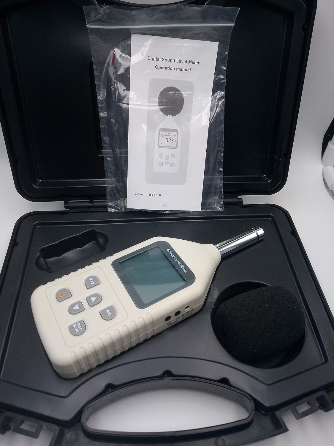
Figure 4: The GM1358 Sound Level Meter, its protective carrying case, and the included operation manual.
The device comes with a durable carrying case for protection and portability, along with a printed operation manual for detailed instructions.
4. Operating Instructions
4.1. Basic Measurement
- Power On: Press the Power Switch to turn on the meter.
- Select Weighting: Use the A/C button (Equivalent Weight Select Switch, '6' in Figure 2) to toggle between A-weighting (for general noise) and C-weighting (for low-frequency noise). The selected weighting will be indicated on the LCD.
- Select Response Time: Use the FAST/SLOW button to choose between Fast (for rapidly changing noise) and Slow (for stable noise) response times. The selected mode will be indicated on the LCD.
- Select Range: Use the Level Range Control Switch ('4' in Figure 2) to select an appropriate measurement range. If "OVER" or "UNDER" is displayed, adjust the range accordingly until a stable reading is obtained.
- Position Microphone: Point the microphone ('1' in Figure 2) towards the sound source you wish to measure.
- Read Measurement: The current sound level will be displayed as the "Measuring Value" ('5' in Figure 3) on the LCD.
4.2. Max Hold Function
To capture and hold the maximum sound level detected during a measurement period:
- While measuring, press the MAX button (Maximum Value Hold Switch, '5' in Figure 2).
- The "MAX" indicator ('4' in Figure 3) will appear on the LCD, and the display will show the highest sound level recorded since MAX was activated.
- Press the MAX button again to exit Max Hold mode and return to real-time measurement.
4.3. AC/DC Output
The GM1358 provides AC and DC output ports for connecting to external devices such as frequency analyzers, level recorders, FFT analyzers, or graphic recorders. These outputs allow for further analysis and recording of sound data.
- AC Output: Provides an AC signal proportional to the sound level, suitable for waveform analysis.
- DC Output: Provides a DC voltage proportional to the sound level, suitable for logging or trend analysis.
Consult the specifications of your external recording device for proper connection and calibration.
5. Maintenance and Care
- Cleaning: Wipe the device with a soft, dry cloth. Do not use abrasive cleaners or solvents.
- Storage: When not in use for extended periods, remove the battery to prevent leakage. Store the meter in its protective carrying case in a cool, dry place, away from direct sunlight and extreme temperatures.
- Microphone Protection: Always keep the microphone clean and free from dust or debris. Use the foam windscreen provided to protect the microphone and reduce wind noise during outdoor measurements.
- Calibration: For professional applications requiring high accuracy, periodic calibration by a qualified laboratory is recommended.
6. Troubleshooting
| Problem | Possible Cause | Solution |
|---|---|---|
| Device does not power on. | Low or dead battery; incorrect battery installation. | Replace the 9V battery; ensure correct polarity. |
| "UNDER" or "OVER" displayed. | Sound level is outside the current measurement range. | Adjust the Level Range Control Switch to a suitable range. |
| Inaccurate readings. | Microphone obstructed; incorrect weighting/response time; need for calibration. | Ensure microphone is clear; select appropriate A/C weighting and Fast/Slow response; consider professional calibration. |
| Display is dim or flickering. | Low battery. | Replace the 9V battery. |
7. Specifications
| Parameter | Value |
|---|---|
| Measuring Range | 30 to 130dBA / 35 to 130dBC |
| Accuracy | ±1.5dB |
| Frequency Range | 31.5Hz ~ 8.5KHz |
| Resolution | 0.1dB |
| Frequency Weighting | A / C |
| Sampling Frequency | 2 times/sec |
| Dynamic Characteristic | Fast / Slow |
| Output Function | AC / DC output |
| Power Supply | 9V Battery (not specified if included, common for these devices) |
| Standards | IEC651 TYPE2 & ANSI S1.4 TYPE2 |
8. Warranty and Support
Warranty information for the Benetech GM1358 Digital Sound Level Meter is typically provided with the product packaging or can be found on the official Benetech website. Please refer to the documentation included with your purchase for specific warranty terms and conditions.
For technical support, troubleshooting assistance beyond this manual, or inquiries regarding repairs and parts, please contact Benetech customer service or your authorized dealer. Contact details are usually available on the manufacturer's website or the product packaging.
Ask a question about this manual
Ask about setup, troubleshooting, compatibility, parts, safety, or missing instructions. Manuals+ will review the question and use this page’s manual context to help answer it.