1. Introduction
The PZEM-004T Current Voltage Power Energy Multimeter Module is designed for comprehensive measurement of AC electrical parameters. It provides accurate readings for voltage, current, active power, and energy consumption. Equipped with a TTL serial communication interface, this module allows for easy integration into various systems for data acquisition and control. Its robust design and high current capacity make it suitable for monitoring a wide range of electrical loads.
2. Safety Information
WARNING: This device operates with AC mains voltage (80-260V). Improper handling can result in electric shock, serious injury, or death. Always follow these safety guidelines:
- Ensure power is disconnected before installation or wiring.
- Installation should only be performed by qualified personnel.
- Do not touch live terminals or components when power is applied.
- Verify all connections are secure and correct before applying power.
- Do not exceed the maximum rated voltage (260V AC) or current (100A).
- Keep the module away from moisture and extreme temperatures.
- Use appropriate personal protective equipment (PPE) during installation.
3. Product Overview
The PZEM-004T module consists of the main measurement board and a current transformer (CT). The module measures electrical parameters, while the CT is used to non-invasively measure current flowing through a conductor.

Figure 3.1: PZEM-004T Multimeter Module and accompanying Current Transformer (CT). The module is a green circuit board with various electronic components and terminal blocks. The CT is a black toroidal coil with red and black wires.
3.1. Module Components
- TTL Serial Interface (P2): Used for communication with external devices (e.g., microcontrollers, computers) to read and set parameters. Includes 5V, RX, TX, and GND pins.
- AC Input Terminals (P4): Connects to the AC 80-260V power supply for voltage measurement and module operation.
- Current Transformer (CT) Input (P1): Connects to the external current transformer for current measurement.
- Energy Reset Button: A small button on the module (not explicitly visible in all images but mentioned in features) to reset the accumulated energy reading.

Figure 3.2: Top view of the PZEM-004T Multimeter Module, showing the TTL serial interface on the left, the main circuit board, and the AC input terminals on the right. A "Q.C. Passed" sticker is visible in the center.
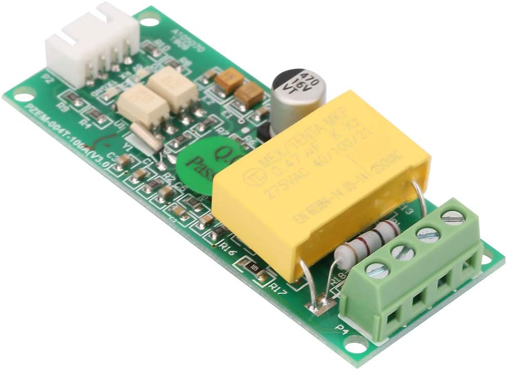
Figure 3.3: Bottom view of the PZEM-004T Multimeter Module, showing the solder points and circuit traces.
4. Setup and Wiring
Proper wiring is crucial for accurate measurement and safe operation. Refer to the wiring diagram below.
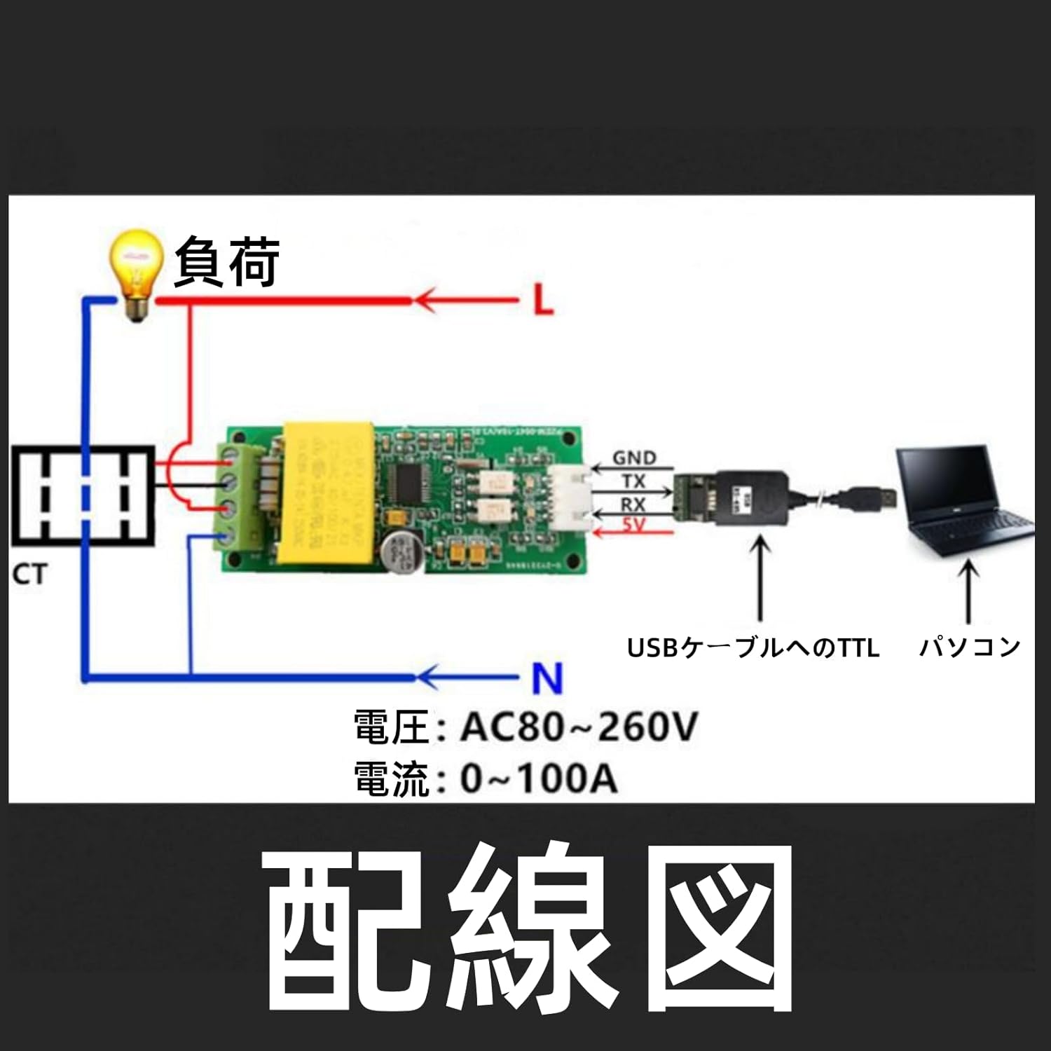
Figure 4.1: Wiring diagram for the PZEM-004T module. The diagram shows the AC power input (AC 80-260V) connected to the module's L and N terminals. The current transformer (CT) is shown clamped around the live (L) wire of the load. The module's TTL interface (GND, TX, RX, 5V) is connected to a TTL to USB cable, which then connects to a computer for data communication.
4.1. Connection Steps
- Connect the Current Transformer (CT): Pass the live wire (L) of the circuit you wish to measure through the hole of the current transformer. Connect the two wires from the CT to the CT input terminals (P1) on the PZEM-004T module. Ensure correct polarity if specified, though for most CTs, direction affects current reading sign, not magnitude.
- Connect AC Power Input: Connect the AC 80-260V power supply to the AC input terminals (P4) of the module. Ensure the Live (L) and Neutral (N) connections are correct. This powers the module and allows it to measure voltage.
- Connect TTL Serial Interface (Optional): If you intend to communicate with the module via serial, connect the TTL serial interface (P2) to a suitable TTL-to-USB converter or microcontroller.
- 5V: Power supply for external device (if needed, typically output from module).
- RX: Receive data (connect to TX of external device).
- TX: Transmit data (connect to RX of external device).
- GND: Ground connection.
Note: The module can operate and display measurements without the TTL serial connection, but data logging or remote control requires it.

Figure 4.2: The PZEM-004T module connected via a TTL-to-USB adapter to a laptop, demonstrating a typical setup for data communication and monitoring.
5. Operating Instructions
Once properly wired and powered, the PZEM-004T module will begin measuring and displaying electrical parameters. Data can be read via the TTL serial interface.
5.1. Data Reading via TTL Serial
The module communicates using a standard serial protocol. You will need a serial terminal program or a custom application to interact with it. Common serial parameters are:
- Baud Rate: 9600 bps (common, verify with module documentation if available)
- Data Bits: 8
- Parity: None
- Stop Bits: 1
Specific commands for reading voltage, current, power, and energy, as well as for resetting energy, will depend on the module's firmware. Refer to the manufacturer's detailed communication protocol documentation for precise commands and data formats.
5.2. Energy Reset Feature
The module includes a physical button for resetting the accumulated energy (kWh) reading. Locate the small button on the module (often labeled "RESET" or similar, or simply a tactile switch). Pressing this button will clear the energy accumulation to zero.
Note: This reset typically only affects the energy reading, not other parameters like voltage or current.
Video 5.1: An overview of the PZEM-004T Current Voltage Power Energy Multimeter Module, demonstrating its physical appearance and key features. This video provides a visual guide to the product.
6. Maintenance
The PZEM-004T module is designed for long-term, reliable operation with minimal maintenance. However, adhering to these guidelines will ensure optimal performance and longevity:
- Keep Clean: Periodically clean the module with a soft, dry cloth. Avoid using liquids or abrasive cleaners.
- Environmental Conditions: Ensure the module is operated within its specified temperature and humidity ranges. Avoid dusty or corrosive environments.
- Connection Integrity: Regularly check all wiring connections for tightness and signs of corrosion or damage. Loose connections can lead to inaccurate readings or safety hazards.
- Firmware Updates: While not typically user-updatable, if manufacturer-provided firmware updates become available, follow their instructions carefully.
7. Troubleshooting
If you encounter issues with your PZEM-004T module, refer to the following common problems and solutions:
| Problem | Possible Cause | Solution |
|---|---|---|
| No readings/Module not powering on | No AC input power; Incorrect AC wiring; Faulty module. | Verify AC 80-260V power supply is connected and active. Check AC input terminal connections (L/N). Test module with a known good power source. |
| Current reading is zero or incorrect | CT not connected; CT not properly installed around live wire; Faulty CT. | Ensure CT wires are securely connected to the module's CT input. Verify the live wire passes through the CT. Check CT for damage. |
| Serial communication issues | Incorrect wiring (RX/TX swapped); Incorrect baud rate/serial settings; Driver issues for USB-TTL converter. | Double-check RX/TX connections (TX of module to RX of converter, RX of module to TX of converter). Confirm serial port settings (baud rate, data bits, parity, stop bits). Install/update USB-TTL converter drivers. |
| Energy reading not resetting | Button not pressed correctly; Module malfunction. | Ensure the reset button is pressed firmly. If the issue persists, contact support. |
8. Specifications
| Parameter | Value |
|---|---|
| Operating Voltage | AC 80-260V |
| Max Current | 100A |
| Measurement Parameters | Voltage, Current, Active Power, Energy |
| Communication Interface | TTL Serial |
| Dimensions (L x W x H) | Approx. 2.87 x 1.18 x 0.91 inches (73 x 30 x 23 mm) |
| Weight | Approx. 0.352 ounces (10g) |
| Material | Metal plastic |
| Country of Origin | China |

Figure 8.1: Diagram showing the approximate dimensions of the PZEM-004T module in millimeters.
9. Warranty and Support
For warranty information and technical support, please contact Walfront customer service. Keep your purchase receipt as proof of purchase.
- Brand: Walfront
- Manufacturer: Walfront
- Model Number: Walfrontec37h6rs8d
- Amazon Store: Visit Walfront Store on Amazon
For specific technical inquiries regarding the TTL serial protocol or advanced usage, it is recommended to search for community resources or detailed datasheets provided by the module's original designer (PZEM).
