1. Product Overview
The LDSOLAR SD Series Sky Dream PWM Solar Charge Controller is designed for off-grid solar home systems, traffic indicators, solar street lights, and solar garden lights. It operates in series PWM mode, featuring full digital technology and an LCD display for intuitive operation. The intelligent charging process is optimized for extended battery life and enhanced system performance.
Key Features:
- Advanced CPU: Equipped with a 32-bit CPU for higher sampling precision and faster operation speed.
- Automatic System Voltage Identification: Automatically detects 12V/24V DC system voltage.
- Three-Stage PWM Charging: Utilizes Bulk, Boost, and Float charging stages for optimal battery health.
- Battery Compatibility: Supports Sealed, Gel, and Flooded battery types with selectable charging procedures.
- User-Friendly LCD: Features a humanized LCD display showing dynamic operation data and working status.
- Built-in Operation Log: Records system working state for easy monitoring.
- Multiple Load Control Modes: Includes Normal mode, Sensor mode, and Timer mode.
- Temperature Compensation: Ensures accurate charging based on ambient temperature.
- Comprehensive Protection: Full digital protection functions against overcharging, over-discharging, overload, short circuit, and reverse connection.
- Robust Connectors: Supports up to 16mm² connectors.
- USB Output: Includes a 5V 1A USB output for charging small devices.

Figure 1.1: Front view of the LDSOLAR SD Series Solar Charge Controller, showing the LCD display and control buttons. The unit is dark gray with a blue border around the display.
2. Setup and Installation
Proper installation is crucial for the safe and efficient operation of your solar charge controller. Please follow these steps carefully.
2.1 Unpacking and Inspection
- Carefully unpack the controller and inspect it for any shipping damage.
- Verify that all components listed in the packaging are present.

Figure 2.1: The retail packaging box for the LDSOLAR SD Series Solar Charge Controller, displaying product features and branding.
2.2 Mounting Location
- Mount the controller indoors, away from direct sunlight, high temperatures, and water.
- Ensure adequate ventilation around the controller to dissipate heat.
- Mount the controller vertically on a non-flammable surface.
2.3 Wiring Sequence
WARNING: Connect the components in the following order to prevent damage to the controller or other system components. Always ensure correct polarity.
- Connect the Battery: Connect the battery to the controller's battery terminals first. The controller will automatically detect the system voltage (12V or 24V). Ensure the battery is charged sufficiently (above 10V) for the controller to recognize it.
- Connect the Solar Panel: Connect the solar panel to the controller's PV terminals. Ensure the solar panel voltage is within the controller's specifications (Max Input Voltage: 55V).
- Connect the Load: Connect the DC load to the controller's load terminals. Do not exceed the maximum discharge current.
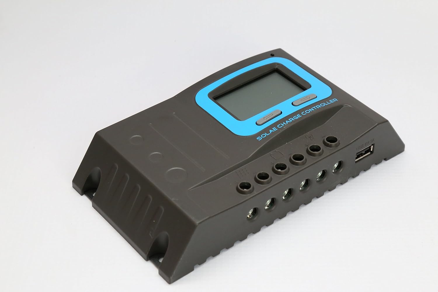
Figure 2.2: Side view of the controller, illustrating the various wiring terminals for battery, solar panel, and load connections, along with the USB output port.
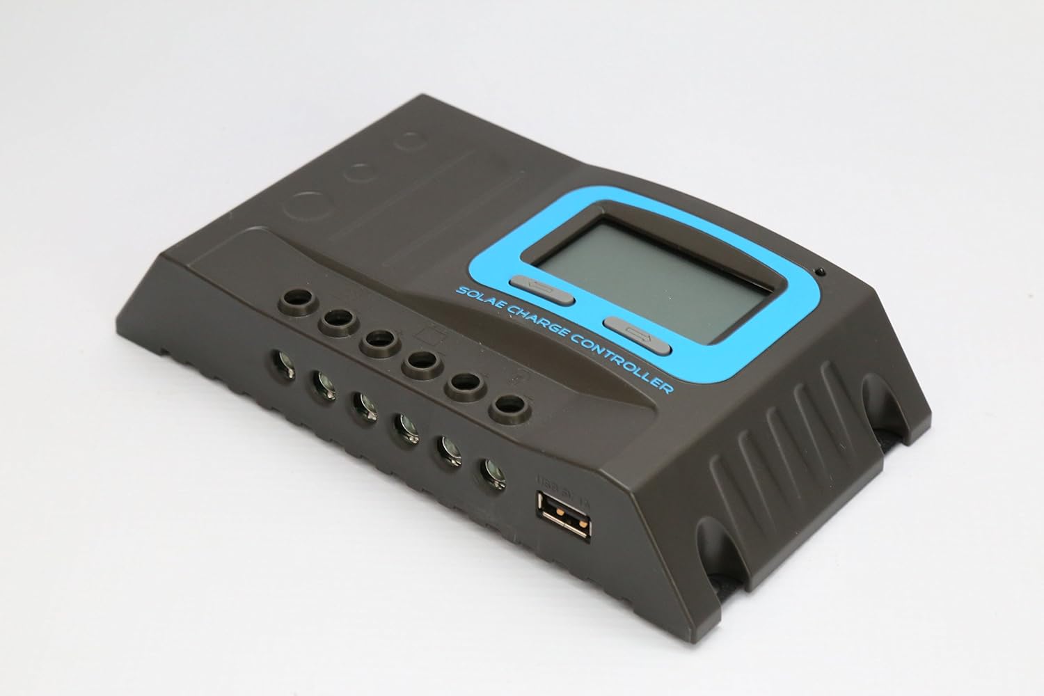
Figure 2.3: An angled perspective of the solar charge controller, highlighting the robust terminal connections and the integrated USB charging port.
2.4 Battery Type Selection
The controller supports Sealed, Gel, and Flooded battery types. Refer to the controller's LCD menu to select the appropriate battery type for optimal charging parameters. Incorrect selection can lead to reduced battery life.
3. Operating Instructions
The LCD display provides real-time system information, and the buttons allow for navigation and setting adjustments.
3.1 LCD Display
The LCD displays various parameters including battery voltage, charging current, discharging current, battery state of charge, and load status. Cycle through the display screens using the navigation buttons.
3.2 Button Functions
- Menu Button: Press to enter the menu or confirm a setting.
- Up/Down Buttons: Use to navigate through menu options or adjust values.
3.3 Load Control Modes
The controller offers several load control modes:
- Normal Mode: Load is continuously ON.
- Sensor Mode: Load turns ON/OFF based on light conditions (e.g., dusk to dawn).
- Timer Mode: Load turns ON at dusk and stays ON for a set duration.
Refer to the on-screen menu for detailed configuration of each mode.
3.4 USB Output
The integrated 5V 1A USB port can be used to charge small electronic devices. This output is active when the controller is powered.
4. Maintenance
Regular maintenance ensures the longevity and optimal performance of your solar charge controller.
- Check Connections: Periodically inspect all wiring connections to ensure they are tight and free from corrosion.
- Cleanliness: Keep the controller clean and free from dust and debris. Use a dry cloth for cleaning.
- Ventilation: Ensure that the ventilation openings are not blocked to allow for proper heat dissipation.
- Battery Health: Monitor battery voltage and performance regularly. Ensure the battery type setting on the controller matches your battery.
5. Troubleshooting
This section addresses common issues you might encounter with your solar charge controller.
5.1 Common Issues and Solutions
- No Display/No Power:
- Check battery connections and ensure battery voltage is above 10V.
- Verify battery polarity.
- Battery Not Charging:
- Check solar panel connections and polarity.
- Ensure there is sufficient sunlight on the solar panels.
- Verify solar panel voltage is within the controller's input range.
- Load Not Working:
- Check load connections and polarity.
- Ensure the load current does not exceed the controller's maximum discharge current.
- Check the load control mode settings (Normal, Sensor, Timer).
- The controller has Load Over Current Protection; it will auto-restart every 30 seconds if an overload is detected. Reduce the load.
- Error Codes: The controller's built-in operation log and LCD display may show error codes. Refer to the specific error code meanings in the full product manual (if available) or contact customer support.
6. Technical Specifications
| Specification | Value |
|---|---|
| Model | SD2430C |
| System Voltage | 12V/24V (Automatic Identification) |
| PV Max Input Voltage | 55V |
| Self-consumption | ≤12mA |
| Max Charge Current | 30A |
| Max Discharge Current | 20A |
| Low Voltage Disconnection (LVD) | 11.0V ADJ (9V-12V); ×2/24V |
| Low Voltage Reconnection (LVR) | 12.6V ADJ (11V-13.5V); ×2/24V |
| Float Voltage | 13.8V ADJ (13V-15V); ×2/24V |
| Boost Voltage | 14.4V; ×2/24V (auto boost for 2 hours if battery voltage < 12.6V) |
| Battery Over Voltage Disconnection | 16.5V; ×2/24V |
| Reverse Connection Protection | Yes |
| Load Over Current Protection | Yes, auto restart every 30s |
| Charge Type | PWM |
| Temperature Compensation | -24 mV /℃ for 12V system; ×2/24V |
| Working Temperature | -20℃ to +55℃ |
| Terminal Scale | 14-6 AWG (16mm²) |
| Waterproof Grade | IP32 |
| Product Dimensions | 190mm × 108mm × 41.5mm (7.48 x 4.25 x 1.63 inches) |
| Net Weight | 450g (15.8 ounces) |
| Manufacturer | LDSOLAR |
| UPC | 652042950784 |
* Please ensure the product is used under its rated power, especially in high-temperature environments.
7. Warranty and Support
Information regarding product warranty and customer support was not provided in the available data. Please refer to the product packaging or the manufacturer's official website for warranty details and contact information for technical support.