1. Introduction
This manual provides essential information for the safe and efficient use of the AKO 15226 Electronic Controller DI IP2. Please read these instructions carefully before installation, operation, or maintenance to ensure proper functioning and to prevent damage to the device or injury to personnel. Keep this manual in an accessible location for future reference.
2. Safety Information
Always observe the following safety precautions:
- Electrical Safety: Installation and maintenance must be performed by qualified personnel only. Disconnect power before performing any work on the device.
- Voltage: Ensure the power supply matches the device's specified voltage (AC 230V).
- Environment: Do not expose the device to excessive moisture, dust, or extreme temperatures beyond its operating range. The device has an IP2 protection rating, indicating limited protection against solid objects and no protection against liquids.
- Mounting: Securely mount the device on a DIN rail as specified to prevent accidental dislodgement.
- Intended Use: Use the controller only for its intended purpose as an electronic regulator for industrial applications.
3. Product Overview
The AKO 15226 is a versatile electronic controller designed for precise regulation in various industrial and scientific applications. It features a clear 3.5-digit display and supports a wide range of universal sensors, including NTC, PTC, Pt100, and TC(J,K).
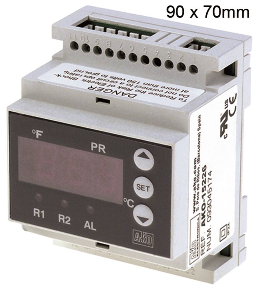
Figure 3.1: Front view of the AKO 15226 Electronic Controller. This image shows the compact design suitable for DIN rail mounting, with its digital display and control interface.
Key Features:
- Display: 3.5-digit indicator for clear readings.
- Mounting Type: Designed for DIN rail installation.
- Dimensions: Installation dimensions of 90 x 70 x 58 mm.
- Installation Depth: 61.5 mm.
- Sensor Compatibility: Universal sensor input for NTC, PTC, Pt100, and TC(J,K)/mA.
- Output: Two CO-8A (4) relay outputs.
- Precision: 1% accuracy.
- Power Supply: AC 230V.
- Protection Rating: IP2.
4. Setup
Follow these steps for proper installation of the AKO 15226 controller:
- Power Disconnection: Ensure all power to the installation area is disconnected before beginning.
- Mounting: Mount the controller securely onto a standard DIN rail. Ensure it clicks into place firmly.
- Wiring Power: Connect the AC 230V power supply to the designated terminals on the controller. Refer to the wiring diagram provided with the device for correct polarity and terminal identification.
- Sensor Connection: Connect your chosen NTC, PTC, Pt100, or TC(J,K)/mA sensor to the universal sensor input terminals. Observe correct wiring for the specific sensor type.
- Output Connections: Connect the devices or systems to be controlled to the two relay output terminals (CO-8A). Ensure proper load capacity and wiring.
- Verification: Double-check all connections for security and correctness before restoring power.
- Power On: Restore power to the system. The controller display should illuminate.
5. Operating Instructions
Once installed and powered, the AKO 15226 controller is ready for operation. The 3.5-digit display shows the current measured value from the connected sensor. Specific operating modes and parameter settings are typically accessed via front panel buttons (if present) or through a dedicated configuration interface.
- Display Reading: The primary display indicates the real-time value from the connected sensor (e.g., temperature, pressure).
- Parameter Adjustment: Consult the detailed programming guide (usually a separate document or integrated into the full manual) for instructions on setting control parameters such as setpoints, hysteresis, and alarm thresholds.
- Relay Outputs: The two relay outputs will activate or deactivate based on the configured control logic and the measured sensor value.
- Status Indicators: Observe any LED indicators on the front panel for operational status, alarm conditions, or relay activation.
6. Maintenance
Regular maintenance ensures the longevity and reliable operation of your AKO 15226 controller.
- Cleaning: Periodically clean the exterior of the controller with a soft, dry cloth. Do not use abrasive cleaners or solvents. Ensure no liquids enter the device.
- Inspection: Regularly inspect wiring connections for any signs of wear, corrosion, or looseness. Tighten connections as necessary.
- Environmental Check: Verify that the operating environment remains within the specified temperature and humidity ranges.
- Sensor Calibration: If accuracy is critical, periodically check and recalibrate the connected sensors according to their respective manufacturer's guidelines.
- Firmware Updates: Check the manufacturer's website for any available firmware updates, though this model typically does not support user-updatable firmware.
7. Troubleshooting
If you encounter issues with your AKO 15226 controller, refer to the table below for common problems and their solutions.
| Problem | Possible Cause | Solution |
|---|---|---|
| Display is off | No power supply; Incorrect wiring | Check power connections and supply voltage; Verify wiring against diagram. |
| Incorrect sensor reading | Faulty sensor; Incorrect sensor type selected/wired; Loose sensor connection | Test sensor; Ensure correct sensor type is connected and configured; Check sensor wiring. |
| Relay outputs not activating | Incorrect setpoint/hysteresis; Faulty relay; No power to load | Adjust control parameters; Test relay functionality; Check power to the connected load. |
| Device not responding | Internal fault; Power surge | Disconnect power for 5 minutes, then reconnect; If problem persists, contact technical support. |
8. Specifications
Detailed technical specifications for the AKO 15226 Electronic Controller:
| Feature | Detail |
|---|---|
| Manufacturer | AKO |
| Model Number | 4251391263123 |
| Display | 3.5 digits |
| Mounting Type | DIN rail |
| Installation Dimensions | 90 x 70 x 58 mm |
| Installation Depth | 61.5 mm |
| Sensor Input | Universal (NTC/PTC/Pt100/TC(J,K)/mA) |
| Precision | 1% |
| Relay Outputs | 2 x CO-8A (4) |
| Voltage Type | AC 230 V |
| Protection Rating | IP2 |
| ASIN | B073Z772ZZ |
9. Warranty and Support
AKO products are manufactured to high-quality standards. For specific warranty terms and conditions, please refer to the documentation provided with your purchase or visit the official AKO website. In case of technical issues or questions not covered in this manual, please contact AKO customer support or your authorized distributor.
Please have your model number (AKO 15226) and serial number (if applicable) ready when contacting support for faster service.


