1. Introduction
This manual provides essential information for the proper installation, operation, and maintenance of the Dialight 553 Series Yellow Green LED Circuit Board Inductor. Please read this manual thoroughly before using the product to ensure safe and efficient performance. Retain this manual for future reference.
2. Product Overview
2.1. Components and Features
The Dialight 553 Series LED Circuit Board Inductor is a compact electronic component designed for direct mounting onto circuit boards. It features two LEDs, one yellow and one green, providing dual-color indication. The design incorporates an 80-degree viewing angle and operates efficiently at 10 mA.
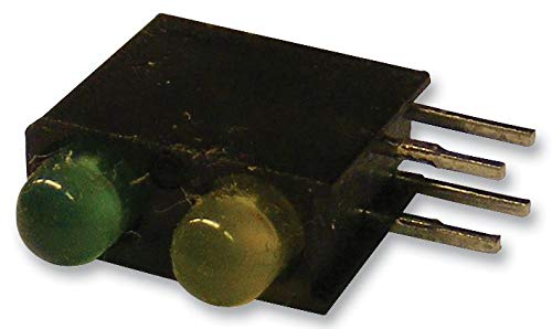
Figure 2.1: The Dialight 553 Series LED Circuit Board Inductor, showing the yellow and green LED lenses and the four metal pins for circuit board mounting.
Key features include:
- Dual-color indication: Yellow and Green LEDs.
- Compact 3 mm size.
- Wide 80-degree viewing angle.
- Low current operation: 10 mA.
- Designed for circuit board mounting with four pins.
3. Setup
3.1. Installation Guidelines
Proper installation is crucial for the longevity and performance of the LED inductor. Follow these guidelines:
- Preparation: Ensure the circuit board is clean and free of debris. Verify that the mounting holes align with the inductor's pins.
- Orientation: Observe the polarity and orientation markings on the inductor and the circuit board. Incorrect orientation can prevent proper function or damage the component.
- Mounting: Carefully insert the four pins of the inductor into the corresponding holes on the circuit board. Ensure all pins are fully seated.
- Soldering: Solder each pin securely to the circuit board using appropriate soldering techniques. Avoid excessive heat, which can damage the LEDs or the plastic housing. Ensure good solder joints for reliable electrical connection.
- Post-Installation Check: After soldering, inspect the connections for any shorts or cold solder joints.
Note: It is recommended to use an anti-static mat and wrist strap during installation to prevent electrostatic discharge (ESD) damage to sensitive electronic components.
4. Operating
4.1. Functional Operation
The Dialight 553 Series LED Inductor functions as a visual indicator when supplied with the correct electrical current. Each LED (yellow and green) operates independently or can be controlled simultaneously depending on the circuit design.
- Current Requirement: Each LED is designed to operate optimally at 10 mA. Exceeding this current can shorten the lifespan of the LED or cause immediate failure.
- Voltage: The forward voltage drop across the LEDs will vary based on the color and current. Always use a current-limiting resistor in series with the LED to ensure the current does not exceed 10 mA.
- Polarity: LEDs are diodes and are polarity-sensitive. Ensure the anode (+) and cathode (-) connections are correctly made to the power source. Incorrect polarity will prevent the LED from illuminating.
- Viewing Angle: The 80-degree viewing angle ensures visibility from a wide range of perspectives.
Consult your circuit diagram for specific voltage and current requirements for your application.
5. Maintenance
5.1. Care and Handling
The Dialight 553 Series LED Inductor is a robust component, but proper care ensures its longevity:
- Cleaning: If necessary, gently clean the LED lenses with a soft, lint-free cloth. Avoid abrasive cleaners or solvents that could damage the plastic.
- Storage: Store unused inductors in their original packaging or in anti-static bags in a cool, dry environment, away from direct sunlight and extreme temperatures.
- Physical Stress: Avoid bending or applying excessive force to the pins or the body of the inductor, as this can cause internal damage.
- Thermal Management: While LEDs are efficient, ensure adequate ventilation around the circuit board, especially in applications where multiple components generate heat.
6. Troubleshooting
6.1. Common Issues and Solutions
If the LED inductor is not functioning as expected, refer to the table below for common issues and their potential solutions:
| Problem | Possible Cause | Solution |
|---|---|---|
| LED does not illuminate. | Incorrect polarity. Insufficient current. Faulty solder joint. Damaged LED. | Verify anode/cathode connections. Check current-limiting resistor value and power supply. Re-solder connections. Replace the inductor if damaged. |
| LED is dim. | Current is too low. Voltage drop across resistor is too high. | Check current-limiting resistor value. Ensure power supply provides adequate voltage. |
| LED flickers or is unstable. | Loose connection. Unstable power supply. | Inspect and re-solder connections. Use a regulated power supply. |
If the issue persists after attempting these solutions, contact a qualified electronics technician or the manufacturer's support.
7. Specifications
7.1. Technical Data
The following table outlines the key technical specifications for the Dialight 553 Series Yellow Green LED Circuit Board Inductor:
| Characteristic | Value |
|---|---|
| Model Number | 553-0744F |
| ASIN | B073QYFBPZ |
| LED Colors | Yellow, Green |
| Size | 3 mm |
| Viewing Angle | 80° |
| Operating Current | 10 mA (per LED) |
| Mounting Type | Circuit Board (Through-hole) |
| Date First Available | May 18, 2020 |
8. Warranty Information
Warranty terms and conditions for the Dialight 553 Series LED Circuit Board Inductor are provided by the manufacturer, Dialight. For detailed warranty information, including coverage period and claims procedures, please refer to the official documentation supplied with your purchase or visit the official Dialight website.
9. Support and Contact
For technical assistance, product inquiries, or further support regarding your Dialight 553 Series LED Circuit Board Inductor, please contact Dialight directly through their official support channels. Up-to-date contact information can typically be found on the Dialight corporate website.
Disclaimer: This manual is intended for informational purposes only. Dialight reserves the right to make changes to product specifications without prior notice.


