Introduction
This manual provides detailed instructions for the safe and efficient operation of your Delock 86108 Network Cable Tester. This device is designed to test various cable types, including RJ45, RJ12, BNC, and USB, for continuity and correct wiring, ensuring reliable network and data connections.
Safety Instructions
- Read all instructions thoroughly before using the device.
- Do not expose the device to moisture, liquids, or extreme temperatures.
- Use only the specified 9V battery type. Incorrect battery usage may damage the device.
- Do not attempt to open or repair the device yourself. Refer all servicing to qualified personnel.
- Keep the device out of reach of children.
Package Contents
- Delock 86108 Network Cable Tester (Main Unit)
- Remote Unit
- User Manual (this document)
Note: Batteries are not included and must be purchased separately.
Product Overview
The Delock 86108 Network Cable Tester consists of a main unit and a detachable remote unit. It features an integrated LED display for indicating test results for various cable types.
Main Unit
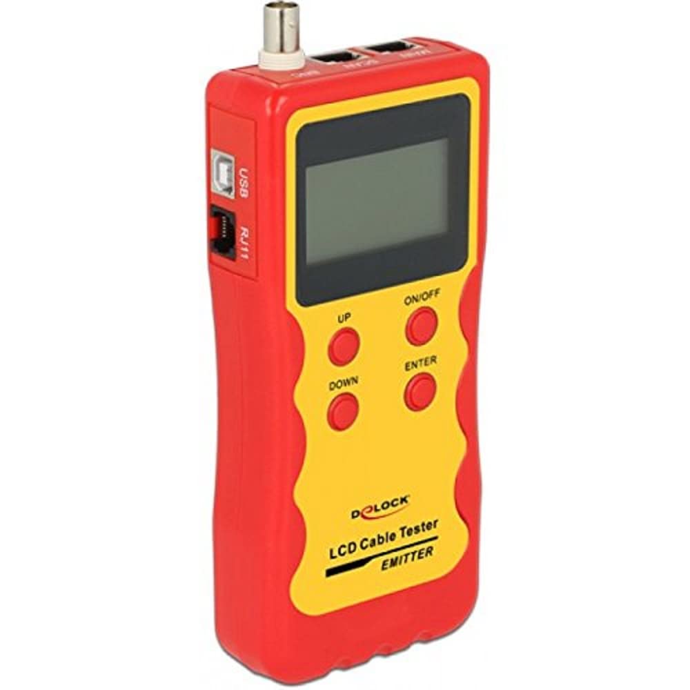
Image Description: A red and yellow Delock 86108 Network Cable Tester main unit, showing the various ports (RJ45, RJ12, BNC, USB) and the LED indicator panel. The device has a robust, handheld design.
Remote Unit
The remote unit detaches from the main unit, allowing for convenient testing of installed cables over longer distances. It typically features corresponding ports to connect the opposite end of the cable being tested.
Setup
Battery Installation
- Locate the battery compartment on the back of the main unit.
- Open the battery compartment cover.
- Insert one 9V battery, ensuring correct polarity (+/-) as indicated inside the compartment.
- Close the battery compartment cover securely.
Powering On/Off
To power on the device, slide the power switch to the "ON" position. The LED indicators will briefly illuminate as a self-test. To power off, slide the switch to the "OFF" position.
Operating Instructions
The Delock 86108 can test various cable types for continuity and correct wiring sequence. Always ensure the tester is powered on before connecting cables for testing.
Testing RJ45/RJ12 Cables
- Connect one end of the RJ45 or RJ12 cable to the corresponding port on the main unit.
- Connect the other end of the cable to the corresponding port on the remote unit. For installed cables, the remote unit can be detached and placed at the other end of the cable run.
- Turn on the tester.
- Observe the LED indicators on both the main and remote units. Each LED corresponds to a specific wire. A sequential illumination of LEDs (1-8 for RJ45, 1-6 for RJ12) on both units indicates correct wiring and continuity.
- If an LED does not light up, it indicates an open circuit (broken wire).
- If LEDs light up out of sequence, it indicates a wiring fault (e.g., crossed pairs, short circuit).
Testing BNC Cables
- Connect one end of the BNC cable to the BNC port on the main unit.
- Connect the other end of the BNC cable to the BNC port on the remote unit.
- Turn on the tester.
- The LED indicators will show continuity for the center conductor and the shield.
Testing USB Cables
- Connect one end of the USB cable (Type A or B, depending on the tester's ports) to the main unit.
- Connect the other end to the remote unit.
- Turn on the tester.
- The LEDs will indicate continuity for the power, data+, data-, and ground lines of the USB cable.
Maintenance
Cleaning
Wipe the device with a soft, dry, lint-free cloth. Do not use abrasive cleaners, solvents, or harsh chemicals, as these can damage the casing or internal components.
Storage
Store the device in a cool, dry place, away from direct sunlight and extreme temperatures. If the device will not be used for an extended period, remove the battery to prevent potential leakage and damage.
Troubleshooting
Device does not power on.
- Check if the 9V battery is correctly installed with the proper polarity.
- Ensure the battery has sufficient charge. Replace with a new 9V battery if necessary.
- Verify the power switch is firmly in the "ON" position.
LEDs do not light up or show inconsistent patterns.
- Ensure all cables are securely connected to both the main and remote units. Loose connections can cause false readings.
- Inspect the cable being tested for visible damage, kinks, or frayed connectors.
- Test with a known good cable to verify the tester's functionality. If the known good cable tests correctly, the issue lies with the original cable.
- Replace the battery if the LEDs appear dim, flicker, or behave erratically, indicating low power.
Specifications
- Model: Delock 86108
- Supported Connectors: BNC, RJ-12, RJ-45, USB
- Display Type: LED indicators
- Power Source: 1 x 9V Battery (not included)
- Dimensions (L x W x H): 185 mm x 80 mm x 32 mm (7.28 in x 3.15 in x 1.26 in)
- Weight: 470 grams (16.58 oz)
- Product Color: Red, Yellow
Warranty and Support
For detailed warranty information, technical support, or service inquiries, please refer to the documentation provided with your original purchase or contact your authorized retailer. Please retain your proof of purchase for any warranty claims.


