1. Introduction
This manual provides comprehensive instructions for the installation, operation, maintenance, and troubleshooting of the U.S. Solid 1/4-inch NPT 3-Way 2-Position DC 24V Pneumatic Electric Solenoid Valve, Model USS-PSV00042. Please read this manual thoroughly before using the product to ensure safe and efficient operation.
2. Product Overview
The U.S. Solid Pneumatic Electric Solenoid Valve is designed for precise control of pneumatic systems. It features a 3-way, 2-position configuration, allowing for efficient air routing and control. Constructed from durable aluminum alloy, this valve is built for longevity and reliable performance in various industrial applications.
Key Features:
- Enhanced Control: Facilitates precise pneumatic control over position, flow, pressure, and temperature.
- Versatile Design: 3/2 valve setup with three port connections and two flow positions.
- Durable Construction: Made from aluminum alloy for reliability and low power consumption.
- Broad Application: Suitable for diverse industries, including aircraft systems and manufacturing.
- User-Friendly: Pre-wired for simplified installation and maintenance.
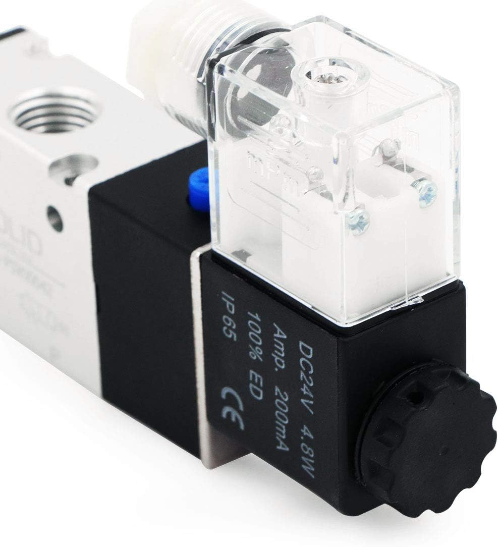
Product Views:


3. Safety Information
Always observe the following safety precautions to prevent injury or damage to the equipment:
- Ensure the power supply is disconnected before installation, maintenance, or troubleshooting.
- Verify that the operating voltage (DC 24V) matches the valve's requirements. Incorrect voltage can damage the coil.
- Do not exceed the maximum operating pressure of 8 bars (0.8 MPa).
- Use appropriate personal protective equipment (PPE) when working with pneumatic systems.
- Ensure all pneumatic connections are secure and leak-free to prevent unexpected pressure release.
- This valve is designed for air. Do not use with incompatible fluids or gases.
4. Installation and Setup
Proper installation is crucial for the valve's performance and longevity. Follow these steps carefully:
4.1. Mounting the Valve
- Mount the valve securely using appropriate fasteners. Ensure it is in a stable position and not subject to excessive vibration.
- Consider the orientation for optimal performance and accessibility for wiring and pneumatic connections.
4.2. Pneumatic Connections
- Identify the inlet (P), outlet (A, B), and exhaust (R, S) ports. The valve is a 3-way, 2-position type, typically having one inlet, one outlet, and one exhaust port.
- Connect 1/4-inch NPT pneumatic lines to the corresponding ports. Use thread sealant tape or compound to ensure airtight connections.
- Ensure the air supply is clean, dry, and within the specified pressure range (0.15-0.8 MPa / 8 Bars maximum).
4.3. Electrical Wiring
The solenoid coil requires a DC 24V power supply. The connector is designed for easy wiring. Refer to the following steps and diagram:
- Disconnect Power: Ensure the DC 24V power supply is completely disconnected before proceeding.
- Remove Connector Cover: Unscrew the small flathead screw on the clear plastic connector cover and carefully pull the cover off the solenoid coil.
- Access Terminals: The internal assembly containing the screw terminals will slide out of the clear plastic housing.
- Connect Wires: Connect the positive (+) and negative (-) wires from your DC 24V power supply to the screw terminals. While polarity generally does not affect solenoid function, if an LED indicator is present, connect the positive wire to the terminal with the resistor attached to prevent LED damage.
- Secure Wires: Tighten the terminal screws to ensure a secure electrical connection.
- Reassemble Connector: Carefully feed the wires through the cable gland and reinsert the internal assembly into the clear plastic housing. Secure the cover with the flathead screw.
- Verify Connections: Double-check all electrical and pneumatic connections before applying power.

5. Operation
The U.S. Solid 3-Way 2-Position Solenoid Valve operates by using an electrical signal to control the internal mechanism, which in turn directs the flow of compressed air.
- De-energized State: When no power is applied to the coil, the valve is in its default (normally closed or normally open) position, directing air flow according to its design.
- Energized State: When DC 24V power is applied to the coil, the solenoid actuates, shifting the valve to its alternative position and redirecting the air flow.
- Manual Override: Some models may include a manual override button (often blue or red) for testing or emergency operation without electrical power. Pressing this button will manually shift the valve position.
Ensure the control system providing the DC 24V signal is properly configured for the desired pneumatic sequence.
6. Maintenance
Regular maintenance helps ensure the longevity and reliable operation of your solenoid valve.
- Inspection: Periodically inspect the valve for any signs of wear, damage, or leaks around the connections.
- Cleaning: Keep the exterior of the valve clean and free from dust and debris. Do not use harsh chemicals that could damage the aluminum alloy or seals.
- Air Quality: Ensure the compressed air supply is consistently clean and dry. Contaminants can cause internal blockages or wear on seals.
- Electrical Connections: Check electrical connections for tightness and corrosion.
- Coil Integrity: Listen for proper actuation when energized. A weak or absent click may indicate a coil issue.
For internal component maintenance, it is recommended to consult a qualified technician or the manufacturer.
7. Troubleshooting
If you encounter issues with your U.S. Solid solenoid valve, refer to the following common problems and solutions:
| Problem | Possible Cause | Solution |
|---|---|---|
| Valve does not actuate (no click sound) | No power to coil, incorrect voltage, faulty coil, loose wiring. | Check DC 24V power supply. Verify wiring connections (refer to Section 4.3). Test coil resistance if possible. Replace coil if faulty. |
| Air leak from ports or body | Loose NPT connections, damaged seals, internal debris. | Tighten NPT connections with thread sealant. Inspect and replace seals if damaged. Ensure air supply is clean. |
| Valve actuates but no air flow change | Internal blockage, incorrect port connections, insufficient air pressure. | Check air supply pressure. Verify pneumatic connections are correct. Disassemble and clean internal components if necessary (by qualified personnel). |
| Valve remains stuck in one position | Debris in valve, weak solenoid, excessive back pressure. | Check for debris. Verify coil is receiving full voltage. Ensure system pressure is within limits. |
8. Specifications
Technical specifications for the U.S. Solid Model USS-PSV00042 Pneumatic Electric Solenoid Valve:
| Feature | Specification |
|---|---|
| Model Number | USS-PSV00042 |
| Material | Aluminum Alloy |
| Voltage | DC 24V |
| Power Consumption | 4.8W (200mA) |
| Inlet Connection Size | 1/4 Inches NPT |
| Outlet Connection Size | 1/4 Inches NPT |
| Number of Ports | 3 |
| Maximum Operating Pressure | 8 Bars (0.8 MPa) |
| Operating Temperature | Not specified (typical for industrial valves) |
| Ingress Protection (IP) Rating | IP65 |
| Item Weight | 7.3 ounces |
| Package Dimensions | 5 x 4.92 x 1.06 inches |
| UPC | 888107084624 |
Dimensions:

IP65 Rating Explanation:

9. Warranty and Support
U.S. Solid offers a 1-year warranty or money-back promise for this product, ensuring customer satisfaction. For technical assistance, troubleshooting beyond this manual, or warranty claims, please contact U.S. Solid customer support through their official website or the retailer where the product was purchased.


