EPEVER VS1024AU
EPEVER Solar Charge Controller VS-AU Series User Manual
Model: VS1024AU
Brand: EPEVER
1. Product Overview

Figure 1: EPEVER VS1024AU Solar Charge Controller
The EPEVER ViewStar AU series is a PWM solar charge controller featuring an integrated LCD display and advanced digital technology. It is designed for various solar applications, including home solar systems, traffic signals, solar street lights, and solar garden lamps.
Key Features:
- 3-Stage intelligent PWM charging: Bulk, Boost/Equalize, Float.
- Supports three battery charging options: Sealed, Gel, and Flooded.
- LCD display dynamically shows device operating data and working conditions.
- Dual USB ports provide power supply for electronic equipment (Max. 2.4A output).
- User-friendly button settings for comfortable and convenient operation.
- Multiple load control modes.
- Energy statistics function.
- Battery temperature compensation function.
- Extensive electronic protections for safe operation.
2. Product Components and Dimensions
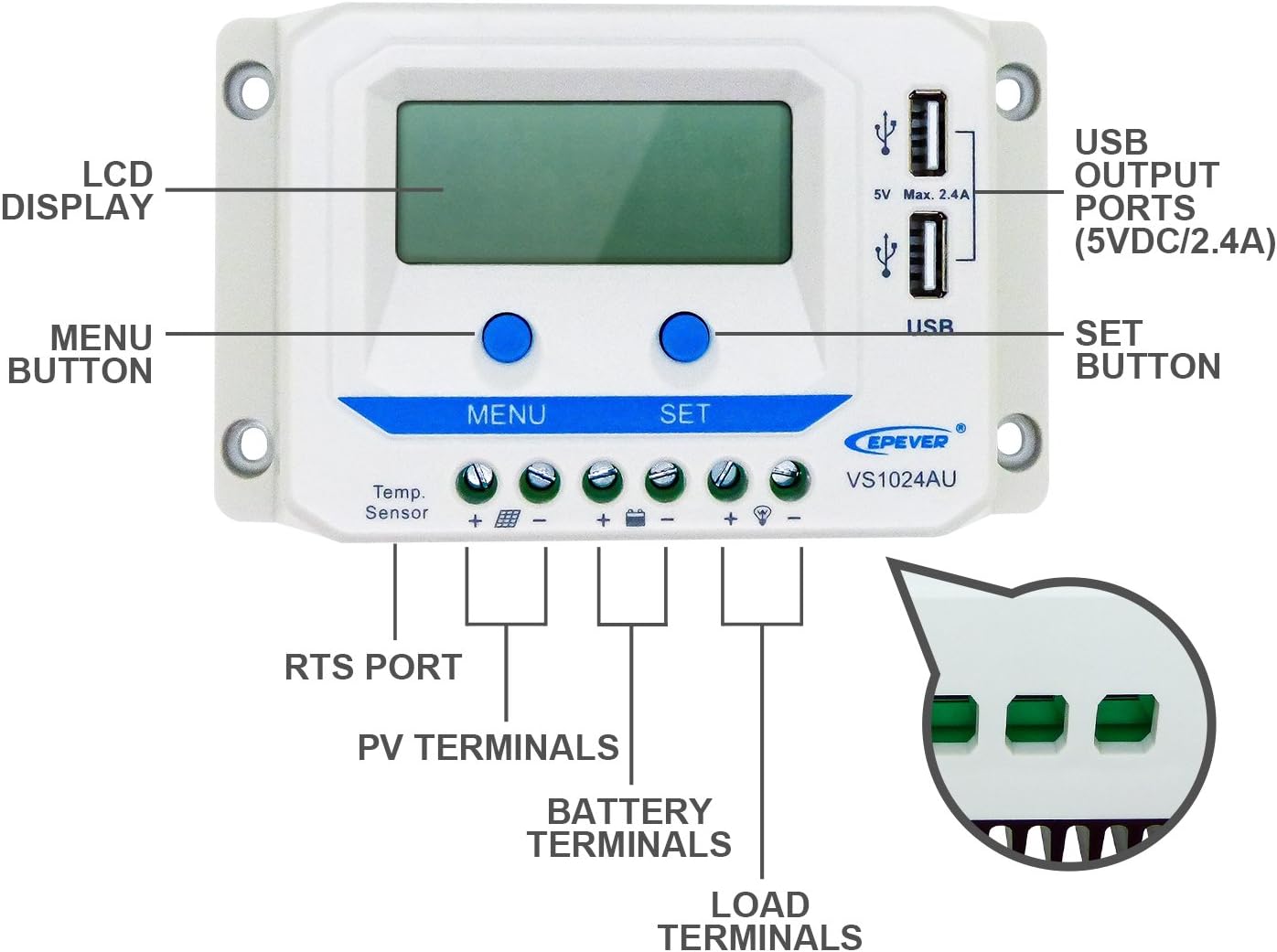
Figure 2: Labeled Components
- LCD DISPLAY: Shows operational data.
- USB OUTPUT PORTS (5VDC/2.4A): For charging external devices.
- MENU BUTTON: Navigates through display interfaces and settings.
- SET BUTTON: Confirms settings and controls load.
- RTS PORT: Remote Temperature Sensor port.
- PV TERMINALS: Connect to solar panel.
- BATTERY TERMINALS: Connect to battery.
- LOAD TERMINALS: Connect to DC load.

Figure 3: Product Dimensions (Approximate)
- Length: 14.2 cm
- Width: 8.5 cm
- Height: 4.15 cm
The controller features a robust design with a heat sink on the back for efficient heat dissipation, as shown in Figure 4.

Figure 4: Top and Bottom Views
3. Setup and Installation
Proper installation is crucial for the safe and efficient operation of your solar charge controller. Always follow the connection sequence carefully.
Connection Diagram:

Figure 5: Connection Diagram
IMPORTANT: Always Connect the Battery First! Do not use an electric screwdriver for connections.
Connecting Steps:
- Connect the Battery: Connect the battery to the controller's battery terminals. Ensure correct polarity (positive to positive, negative to negative). The controller will automatically detect the battery voltage (12V/24V).
Video 1: Connecting the Battery (See 0:52-0:55 in "EPEVER PWM Solar Charge Controller VS-AU Series" video)
This segment demonstrates the proper connection of the battery to the solar charge controller, highlighting the importance of correct polarity.
- Connect the Solar Panel (PV array): Connect the solar panel to the controller's PV terminals. Observe correct polarity.
Video 2: Connecting the Solar Panel (See 1:40-1:45 in "EPEVER PWM Solar Charge Controller VS-AU Series" video)
This video segment illustrates the connection of the solar panel to the controller, emphasizing the correct wiring procedure.
- Connect the Load: Connect the DC load to the controller's load terminals. Ensure correct polarity.
Video 3: Connecting the Load (See 1:12-1:19 in "EPEVER PWM Solar Charge Controller VS-AU Series" video)
This segment demonstrates how to connect your DC load to the controller, ensuring proper electrical connection.
Disconnection Steps:
To disconnect the system, reverse the connection steps:
- Disconnect the Load.
- Disconnect the Solar Panel (PV array).
- Disconnect the Battery.
4. Operating Instructions
Button Functions:
Video 4: Button Functions (See 0:38-0:47 in "EPEVER PWM Solar Charge Controller VS-AU Series" video)
This video segment demonstrates the functions of the MENU and SET buttons, including backlight display and USB output.
- MENU Button: Used to browse through different display interfaces and to enter/exit setting modes.
- SET Button: Used to confirm selections, adjust parameters, and toggle the load ON/OFF.
Interface Browsing:
Press the MENU button to cycle through the various display interfaces, showing real-time data and system status.
Video 5: Interface Browsing (See 1:59-2:19 in "EPEVER PWM Solar Charge Controller VS-AU Series" video)
This video demonstrates how to navigate through the controller's display interfaces to view various system parameters.
The LCD display provides status descriptions for PV array, Battery, and Load:

Figure 6: LCD Status Description
Load Mode Setting:
To enter the load mode setting interface, press and hold the SET button for 5 seconds until the number begins flashing. Then, press the MENU button to select the desired parameter, and press the SET button to confirm.
Video 6: Load Mode Setting (See 2:43-3:15 in "EPEVER PWM Solar Charge Controller VS-AU Series" video)
This video demonstrates how to adjust the load mode settings, including Timer1 and Timer2 options.
Available load modes include:
- Timer 1 (1xx):
- 100: Light ON/OFF
- 101: Load will be on for 1 hour since sunset
- 102: Load will be on for 2 hours since sunset
- ...
- 117: Manual mode (Default: Load ON)
- Timer 2 (2xx):
- 2^^: Disabled
- 201: Load will be on for 1 hour since sunrise
- 202: Load will be on for 2 hours since sunrise
- ...
- 217: Disabled
Please note: Set Light ON/OFF, Test mode and Manual mode via Timer1. Timer2 will be disabled and display "2n".
5. Electronic Protections
The EPEVER VS-AU series controller is equipped with comprehensive electronic protections to ensure system safety and longevity:
- PV reverse polarity protection
- Battery over voltage protection
- Battery over discharge protection
- Battery reverse polarity protection
- Battery overheating protection
- Load overload protection
- Load short circuit protection
- Controller overheating protection

Figure 7: System with Protections and Optional Accessories
6. Specifications
Detailed specifications for the EPEVER VS1024AU Solar Charge Controller:
| Attribute | Value |
|---|---|
| Model | VS1024AU |
| Nominal System Voltage | 12V/24V Auto Work |
| Rated Charge Current | 10A |
| Rated Discharge Current | 10A |
| Battery Voltage Range | 9V~32V |
| Max. PV Voltage | 50V |
| Controller Terminal | 4mm²/12AWG |
| Overall Dimensions (L x W x H) | 142 x 85 x 41.5 mm (5.59 x 3.35 x 1.63 inches) |
| Item Weight | 2.6 pounds |
| Display Type | LCD |
| Material | Gel (Battery Type Support) |
| UPC | 652042950685 |
Note: The controller also supports Sealed and Flooded battery types. Refer to the battery voltage parameters table in the controller's interface for specific settings.
7. Warranty and Support
EPEVER products are supported by authorized sales agents like GolandCentury, who offer the latest versions of controllers, inverters, and accessories.
For technical assistance and support, GolandCentury provides free technical support through their service centers located in Chicago (USA), Munich (Germany), Toronto (Canada), and Melbourne (Australia).
For any issues or inquiries, please contact your authorized dealer or refer to the official EPEVER website for further support resources.
Ask a question about this manual
Ask about setup, troubleshooting, compatibility, parts, safety, or missing instructions. Manuals+ will review the question and use this page’s manual context to help answer it.