1. Introduction
This manual provides essential information for the safe and effective use of the Allen-Bradley 140M-F8E-C45 Circuit Breaker. It is designed for qualified personnel responsible for the installation, operation, and maintenance of electrical equipment. Please read this manual thoroughly before installation or operation.
2. Safety Information
WARNING: Risk of Electric Shock or Fire
- All electrical work must be performed by qualified and authorized personnel in accordance with all applicable national and local electrical codes and regulations.
- Always disconnect power before installing, servicing, or removing this device. Failure to do so may result in serious injury or death.
- Do not operate the circuit breaker if it appears damaged.
- Ensure proper grounding and wiring connections.
- IF AN OVERLOAD OR A FAULT CURRENT INTERRUPTION OCCURS, CIRCUITS MUST BE CHECKED TO DETERMINE THE CAUSE OF THE INTERRUPTION. IF A FAULT CONDITION EXISTS, THE CONTROLLER SHOULD BE EXAMINED AND REPLACED IF DAMAGED TO REDUCE THE RISK OF FIRE OR ELECTRIC SHOCK.
- TO MAINTAIN OVER-CURRENT, SHORT-CIRCUIT AND GROUND-FAULT PROTECTION, THE MANUFACTURER'S INSTRUCTIONS FOR SELECTION OF OVERLOAD AND SHORT CIRCUIT PROTECTION MUST BE FOLLOWED TO REDUCE THE RISK OF FIRE OR ELECTRIC SHOCK.
3. Product Overview
The Allen-Bradley 140M-F8E-C45 is a robust circuit breaker designed for industrial applications, providing essential protection against overcurrents and short circuits. This model is a standard type circuit breaker with a 45 Amp current rating and a single pole configuration.

Figure 3.1: Angled view of the Allen-Bradley 140M-F8E-C45 Circuit Breaker, showing its compact design and terminal connections.
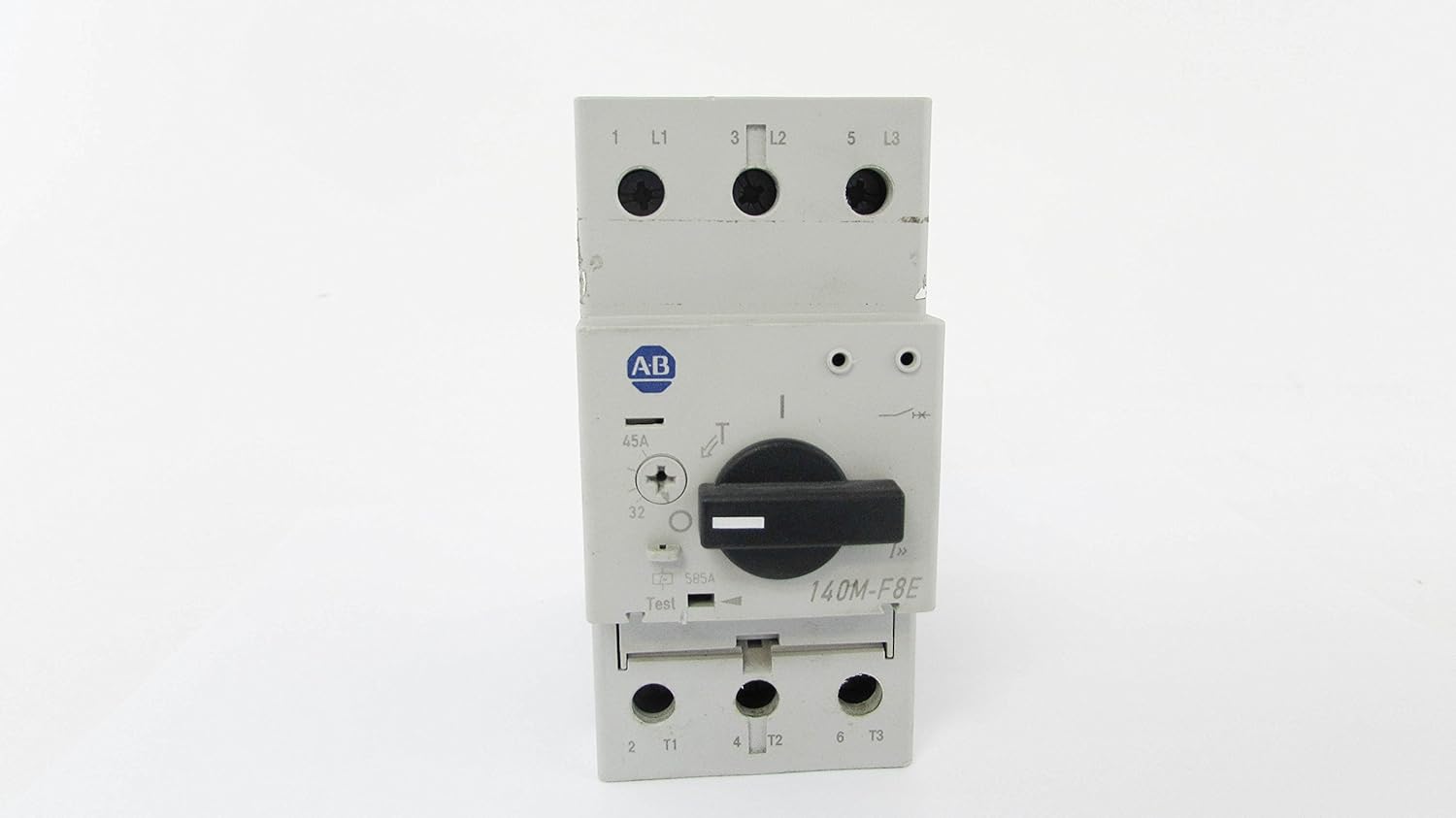
Figure 3.2: Front view of the circuit breaker, highlighting the main switch and rating labels.

Figure 3.3: Detailed view of the product label, displaying model number, current ratings, and compliance standards.

Figure 3.4: Close-up of critical warning labels regarding fault conditions and protection requirements.
4. Setup and Installation
Installation of the 140M-F8E-C45 Circuit Breaker should only be performed by a qualified electrician. Adherence to local and national electrical codes (e.g., NEC, IEC) is mandatory.
4.1 Pre-Installation Checks
- Verify that the circuit breaker's specifications (voltage, current rating) match the requirements of the electrical system.
- Inspect the circuit breaker for any signs of physical damage. Do not install damaged units.
- Ensure all necessary tools and personal protective equipment (PPE) are available.
4.2 Mounting
The circuit breaker is typically mounted on a DIN rail within an appropriate enclosure. Ensure secure mounting to prevent movement or vibration.
4.3 Wiring
- Connect the incoming power supply to the designated input terminals (L1, L2, L3 if applicable).
- Connect the load to the designated output terminals (T1, T2, T3 if applicable).
- Ensure all terminal screws are tightened to the manufacturer's specified torque settings to prevent loose connections and overheating.
- Use appropriate wire gauges for the current rating to prevent overheating.
5. Operating Instructions
The Allen-Bradley 140M-F8E-C45 Circuit Breaker is designed for straightforward operation.
5.1 Turning On the Circuit
To energize the circuit, rotate the operating handle to the 'ON' position. The handle should firmly click into place.
5.2 Turning Off the Circuit
To de-energize the circuit, rotate the operating handle to the 'OFF' position.
5.3 Trip Indication and Reset
In the event of an overload or short circuit, the breaker will automatically trip to protect the circuit. The operating handle will move to an intermediate 'TRIPPED' position. To reset the breaker after a trip:
- First, move the handle fully to the 'OFF' position.
- Investigate and resolve the cause of the trip (e.g., remove overload, fix short circuit).
- Once the fault is cleared, move the handle to the 'ON' position to restore power.
WARNING: Do not repeatedly reset a tripping breaker without identifying and correcting the underlying fault. This can lead to equipment damage or fire.
6. Maintenance
Regular maintenance helps ensure the longevity and reliable operation of your circuit breaker. Always disconnect power before performing any maintenance.
- Visual Inspection: Periodically inspect the circuit breaker for any signs of physical damage, discoloration, or loose connections. Check for dust or debris accumulation.
- Cleaning: Use a dry, lint-free cloth to gently clean the exterior of the circuit breaker. Do not use solvents or abrasive cleaners.
- Terminal Tightness: Periodically check the tightness of all terminal connections. Loose connections can cause overheating and potential failure.
- Functional Test: If equipped with a test button, periodically press it to ensure the trip mechanism is functioning correctly. This should only be done by qualified personnel.
7. Troubleshooting
This section addresses common issues you might encounter with the circuit breaker.
7.1 Breaker Trips Frequently
- Cause: Overload on the circuit.
- Solution: Reduce the load on the circuit by unplugging or turning off some devices.
- Cause: Short circuit in the wiring or a connected device.
- Solution: Disconnect all devices from the circuit and try to reset the breaker. If it still trips, there may be a wiring fault. Consult a qualified electrician.
- Cause: Faulty appliance or equipment.
- Solution: Unplug devices one by one to identify the faulty appliance.
- Cause: Damaged circuit breaker.
- Solution: If the breaker trips without any apparent fault, it may be defective and require replacement by a qualified electrician.
7.2 Breaker Does Not Reset
- Cause: Persistent fault (overload or short circuit) still present.
- Solution: Ensure the handle is moved fully to the 'OFF' position before attempting to reset. Thoroughly investigate and clear the fault.
- Cause: Internal damage to the breaker.
- Solution: If no fault is found and the breaker still won't reset, it may be damaged and needs replacement.
8. Specifications
| Feature | Specification |
|---|---|
| Model Number | 140M-F8E-C45 |
| Brand | Allen-Bradley |
| Current Rating | 45 Amps |
| Circuit Breaker Type | Standard |
| Number of Poles | 1 |
| Product Dimensions | 0.2 x 0.2 x 0.12 inches |
| Item Weight | 1.9 Pounds |
| Manufacturer | ALLEN BRADLEY |
| UPC | 646826316392 |
9. Warranty and Support
For specific warranty information regarding your Allen-Bradley 140M-F8E-C45 Circuit Breaker, please refer to the documentation provided at the time of purchase or contact the authorized Allen-Bradley distributor or the seller directly. Warranty terms typically cover manufacturing defects for a specified period.
For technical support, installation assistance, or to report issues, please contact your authorized Allen-Bradley representative or the supplier from whom the product was purchased. Always provide the model number (140M-F8E-C45) and any relevant serial numbers when seeking support.


