
1. Introduction
This manual provides detailed instructions for the installation, operation, and maintenance of your AMKI DMX 90W Fiber Optic Light Engine. Please read this manual thoroughly before using the product to ensure safe and correct operation.
2. Product Overview
Key Features:
- Multi-color and Dynamic Modes: Offers seven static colors (red, green, blue, white, yellow, cyan, purple), dynamic jump/flash/fade modes, and customizable DIY modes.
- DMX Mode + RF Remote Control: The light engine supports DMX512 signal mode for professional control and includes an RF remote for convenient operation.
- Matching Code Function: Allows for one-to-one remote control pairing with specific light engines.
- Versatile Connectivity: Compatible with DMX512 consoles, PC DMX512 consoles, and DMX decoders.
- High Power 90W: Delivers high brightness, ideal for various fiber optic lighting applications such as star ceilings, curtains, and artistic installations in diverse environments.
What's in the Box:
- 1 x 90W RGB Light Engine (fiber optic cables not included)
- 1 x 28-key RF Remote Control
- 1 x Power Adapter
- 1 x User Manual
Note: Batteries for the remote control are not included.

Figure 2.1: Package Contents and RF Model Connection Diagram. This image illustrates the components included in the package: the light engine, PG connector, remote control, instruction manual, and power adapter.
3. Safety Information
- Ensure the power supply voltage matches the product's requirements (265 Volts).
- Do not expose the light engine to moisture or extreme temperatures.
- Avoid direct eye exposure to the light source.
- Always disconnect power before cleaning or performing any maintenance.
- If you observe sparking or unusual behavior upon connecting power, immediately disconnect the device and contact customer support. Do not attempt to operate a faulty unit.
- Keep out of reach of children.
4. Setup
4.1 Physical Installation
Mount the light engine in a suitable location, ensuring adequate ventilation. Connect the fiber optic cables (not included) to the light engine's output port. Ensure all connections are secure.

Figure 4.1: Product Dimensions and Component Identification. The diagram shows the dimensions of the light engine (280mm x 195mm x 80mm) and identifies key components such as DC24V Power Input, RF Signal Receiver, Bluetooth Signal Receiver, Built-in Sound Sensor, and Indicator Light.
4.2 Power Connection
Connect the provided power adapter to the light engine's DC24V power input. Plug the power adapter into a suitable electrical outlet. Ensure the connection is firm. If any sparking occurs during connection, immediately unplug the unit and contact support.
4.3 Connection Diagrams
The AMKI DMX 90W Fiber Optic Light Engine supports various connection configurations:
4.3.1 DMX Model Connection
For DMX control, connect the light engine to a DMX512 console or PC DMX512 console, potentially through a DMX decoder. Ensure proper DMX signal flow.
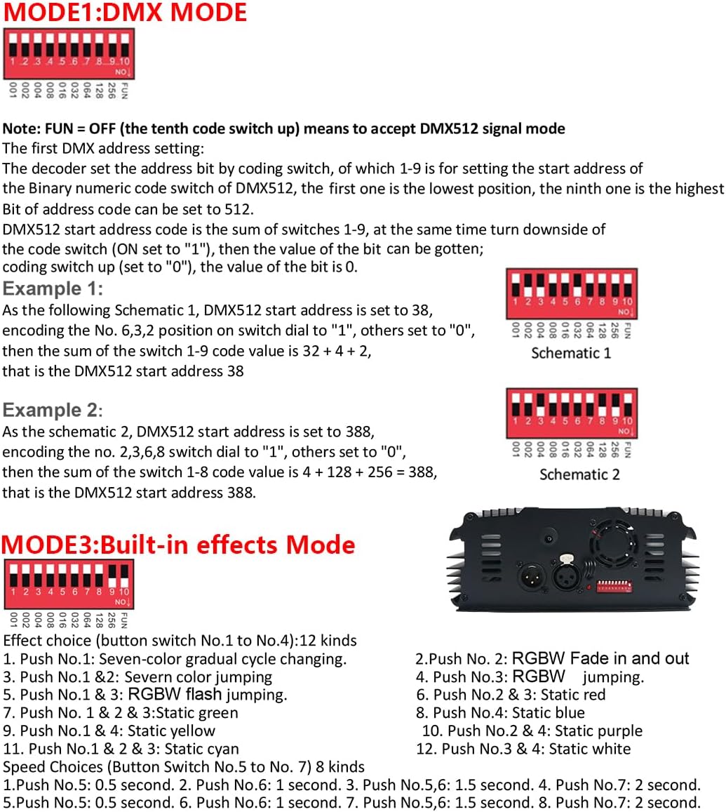
Figure 4.2: DMX Model Connection. This diagram illustrates how to connect the light engine in a DMX setup, including connections to a PC DMX512 console and DMX512 decoders.
4.3.2 RF Model Connection
For RF remote control, the light engine can operate independently or in a master-slave configuration. Refer to Figure 2.1 for the RF Model connection diagram.
4.3.3 Built-in Model Connection
The built-in model allows for standalone operation or master-slave configurations without external DMX control, utilizing the internal effects.

Figure 4.3: Built-in Model Connection. This diagram shows how to connect multiple light engines in a master-slave setup using the built-in effects mode.
5. Operating Instructions
5.1 RF Remote Control Operation
The light engine is controlled by a 28-key RF remote control. Ensure the remote has power (batteries not included) and is within effective range.
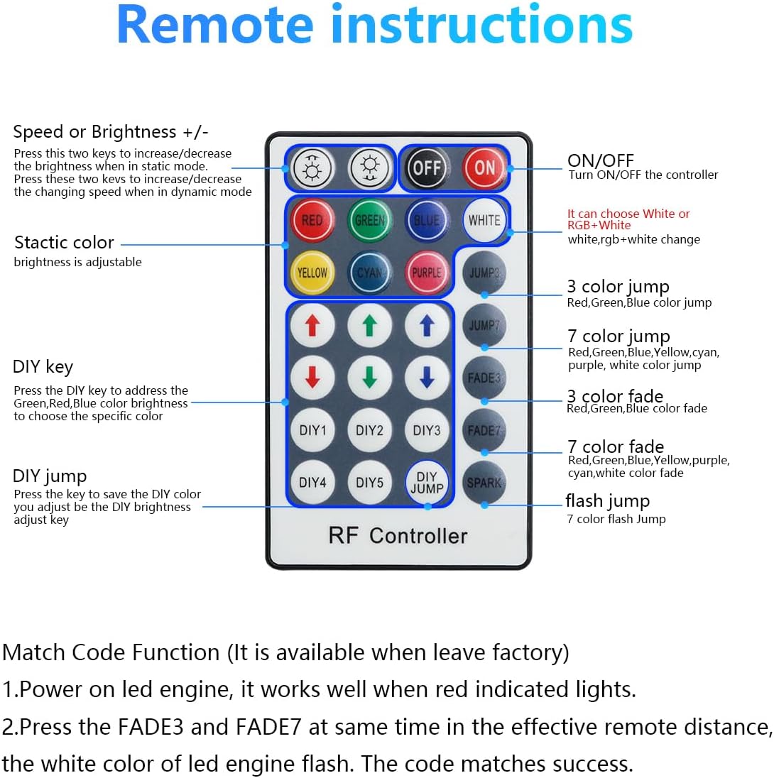
Figure 5.1: RF Remote Control Instructions. This image details the functions of each button on the 28-key RF remote, including ON/OFF, color selection (Red, Green, Blue, White, Yellow, Cyan, Purple), brightness/speed adjustment, jump modes (3-color, 7-color), fade modes (3-color, 7-color), flash jump, and DIY keys.
Remote Functions:
- ON/OFF: Turn the controller on or off.
- Color Buttons (Red, Green, Blue, White, Yellow, Cyan, Purple): Select static colors.
- Speed or Brightness +/-: Adjust brightness in static mode or changing speed in dynamic mode.
- JUMP3: 3-color jump mode (Red, Green, Blue).
- JUMP7: 7-color jump mode.
- FADE3: 3-color fade mode (Red, Green, Blue).
- FADE7: 7-color fade mode.
- FLASH JUMP: 7-color flash jump.
- DIY Keys (DIY1-DIY5): Press to address the Green, Red, Blue color brightness to choose a specific color. Press again to save the DIY color you adjust.
Matching Code Function:
If you need one-to-one control for a specific light engine, you can match the remote control to it. This function is typically available from the factory.
- Power on the LED engine. It works correctly when red lights indicate.
- Press the FADE3 and FADE7 keys simultaneously within the effective remote distance. The LED engine will flash white, indicating successful code matching.
5.2 DMX Mode Operation
The light engine accepts DMX512 signal mode. To use DMX control, you must set the DMX address bit via the coding switch on the unit.
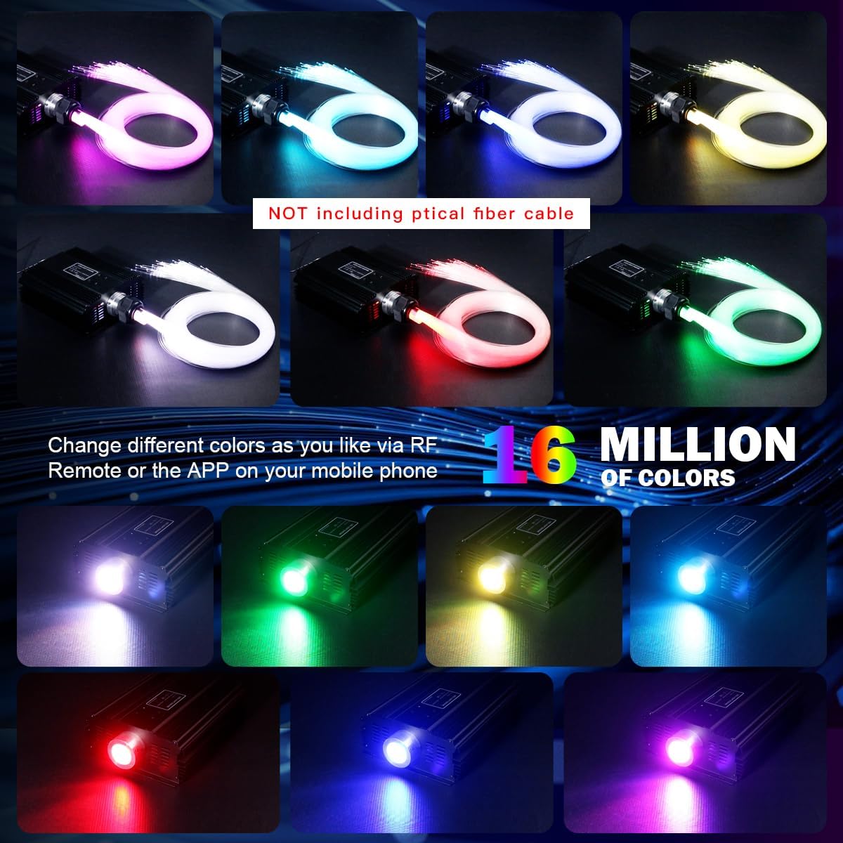
Figure 5.2: DMX Mode and Built-in Effects Mode Settings. This image provides instructions for setting the DMX address using the DIP switches and lists the various built-in effects and speed choices.
DMX Address Setting:
- The decoder sets the address bit via a coding switch. Switches 1-9 are used to set the binary DMX512 start address.
- The first switch represents the lowest position (value 1), and the ninth switch represents the highest position (value 256).
- The tenth switch (labeled FUN) should be set to OFF to accept DMX512 signal mode.
Example 1: To set DMX512 start address to 38, encode switches No. 6, 3, 2 to "ON" and others to "OFF". The sum of switches 1-9 (2 + 4 + 32) equals 38.
Example 2: To set DMX512 start address to 388, encode switches No. 2, 3, 6, 8 to "ON" and others to "OFF". The sum of switches 1-8 (4 + 8 + 64 + 256) equals 388.
5.3 Built-in Effects Mode
When not using DMX control, the light engine can operate using its built-in effects. Refer to Figure 5.2 for the settings.
Effect Choices (Button Switch No.1 to No.4):
- 1. Push No. 1: Seven-color gradual cycle changing
- 2. Push No. 2: RGBW Fade in and out
- 3. Push No. 1 & 2: Seven color jumping
- 4. Push No. 3: RGBW jumping
- 5. Push No. 1 & 3: RGBW flash jumping
- 6. Push No. 2 & 3: Static red
- 7. Push No. 1 & 2 & 3: Static green
- 8. Push No. 4: Static blue
- 9. Push No. 1 & 4: Static yellow
- 10. Push No. 2 & 4: Static purple
- 11. Push No. 1 & 2 & 4: Static cyan
- 12. Push No. 3 & 4: Static white
Speed Choices (Button Switch No.5 to No.7):
- 1. Push No.5: 0.5 second
- 2. Push No.6: 1 second
- 3. Push No.5,6: 1.5 second
- 4. Push No.7: 2 second
- 5. Push No.5,7: 2.5 second
- 6. Push No.6,7: 3 second
- 7. Push No.5,6,7: 3.5 second
6. Maintenance
- Cleaning: Use a soft, dry cloth to clean the exterior of the light engine. Do not use liquid cleaners or solvents.
- Ventilation: Ensure the ventilation openings are clear of dust and debris to prevent overheating.
- Storage: Store the device in a cool, dry place when not in use for extended periods.
7. Troubleshooting
7.1 Remote Control Not Working
If the remote control is not responding:
- Check if the remote control has batteries and if they are correctly inserted.
- Ensure you are within the effective range of the remote control.
- Attempt the matching code function (Section 5.1) to re-pair the remote with the light engine.
7.2 DMX Setup Difficulties
If the light engine is not responding to DMX signals:
- Verify that the DMX address on the light engine is correctly set using the DIP switches (Section 5.2).
- Ensure the FUN switch (tenth switch) is set to OFF for DMX mode.
- Check all DMX cable connections for proper seating and continuity.
- Consult your DMX console or software manual for specific channel assignments and fixture profiles, as this information is not provided with the light engine.
7.3 Power Connection Issues
If the unit does not power on or exhibits unusual behavior upon connection:
- Ensure the power adapter is securely connected to both the light engine and the power outlet.
- Verify that the power outlet is functional.
- If sparking occurs during connection, immediately disconnect the power and contact customer support. Do not attempt to use the unit.
8. Specifications
| Brand | AMKI |
| Model Number | QJ-L090 |
| Color | Multi-color |
| Material | Aluminum |
| Light Source Type | LED |
| Bulb Type | LED |
| Voltage | 265 Volts |
| Maximum Supported Wattage | 90 Watts |
| Included Bulb Wattage | 90 Watts |
| Mounting Type | Tabletop |
| Bulb Features | Remote control, RGB LED |
| Number of Lights | 1 |
| Batteries Included | No |
| Product Weight | 5 Pounds |
| Item Dimensions (L x W x H) | 8.1L x 6.4W x 5.6H cm |
| Finish | Aluminum |
| Style | Classic |
| Manufacturer | Shine Electronics |
| Included Components | Light box |
9. Warranty Information
This AMKI DMX 90W Fiber Optic Light Engine comes with a 2-year warranty from the date of purchase. This warranty covers manufacturing defects and malfunctions under normal use. It does not cover damage caused by misuse, accidents, unauthorized modifications, or improper installation.
Please retain your proof of purchase for warranty claims.
10. Support
For technical support, warranty claims, or any questions regarding your AMKI DMX 90W Fiber Optic Light Engine, please contact your retailer or the manufacturer's customer service.
Please have your model number (QJ-L090) and purchase information ready when contacting support.
