1. Introduction
This manual provides essential instructions for the safe and effective installation, operation, and maintenance of your Hubbell Pressure Switch with Unloader and Lever. This unit is designed as a direct replacement for Ingersoll Rand part number 56288020-01, featuring a 4-port design and an integrated ON/OFF lever. Please read this manual thoroughly before use and retain it for future reference.
2. Safety Information
WARNING: Failure to follow these safety instructions may result in serious injury, death, or property damage.
- Always disconnect power to the compressor or system before attempting any installation, maintenance, or repair.
- Ensure the air system is completely depressurized before working on the pressure switch or any connected components.
- Installation should only be performed by qualified personnel familiar with electrical and pneumatic systems.
- Verify that all electrical connections are secure and comply with local electrical codes.
- Do not exceed the maximum pressure rating of the switch or the compressor system.
- Wear appropriate personal protective equipment (PPE), including eye protection, during installation and maintenance.
- Keep children and unauthorized persons away from the work area.
3. Product Overview
The Hubbell Pressure Switch is a critical component for controlling air compressors. It automatically starts and stops the compressor motor based on system pressure. This model features:
- 4-Port Design: Allows for multiple connections, typically for the main air tank, pressure gauge, safety valve, and unloader line.
- ON/OFF Lever: Provides manual control to start or stop the compressor.
- Unloader Valve: Releases air pressure from the compressor head when the motor stops, allowing for easier restarts.

Figure 1: Front view of the Hubbell 4-Port Pressure Switch. The image shows the black housing with the Hubbell logo, brass fittings for air connections, and the unloader valve assembly.
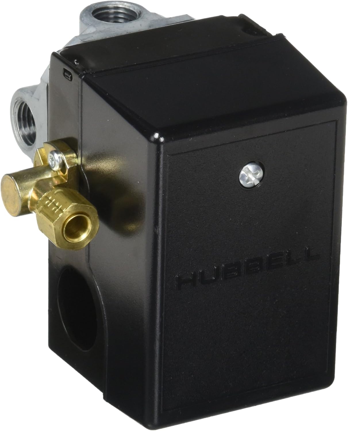
Figure 2: Side view of the Hubbell Pressure Switch, highlighting the electrical screw terminals for wiring connections and additional port details.
4. Setup and Installation
- Preparation:
- Ensure the compressor is turned off and unplugged from its power source.
- Completely drain all air pressure from the compressor tank.
- Carefully remove the old pressure switch, noting the connections for the main air line, unloader line, and electrical wiring. Take photos if necessary for reference.
- Mounting:
- Thread the new Hubbell pressure switch onto the main air tank port. Use thread sealant (e.g., PTFE tape) to ensure an airtight seal.
- Ensure the switch is securely tightened but do not overtighten.
- Pneumatic Connections:
- Connect the unloader line to the appropriate port on the new switch. Note: Some replacement switches may have the unloader port in a different orientation than the original. Minor adjustments to the unloader line may be required.
- Connect any other accessories such as a pressure gauge or safety valve to the remaining ports, using thread sealant as needed.
- Electrical Wiring:
- Open the electrical cover of the pressure switch.
- Connect the compressor motor's power wires to the screw terminals inside the switch. Refer to the wiring diagram provided with your compressor or consult a qualified electrician if unsure.
- Ensure all connections are tight and secure.
- Replace the electrical cover securely.
- Testing:
- With the ON/OFF lever in the "OFF" position, restore power to the compressor.
- Move the ON/OFF lever to the "ON" position. The compressor should start and build pressure.
- Monitor for air leaks at all connections using soapy water. Tighten connections if leaks are detected.
- Observe the compressor's cut-out pressure and cut-in pressure to ensure it operates within the desired range.
5. Operating Instructions
The Hubbell Pressure Switch is designed for straightforward operation.
- To Start the Compressor: Ensure the compressor is plugged into a suitable power source. Move the ON/OFF lever to the "ON" position. The compressor motor will start and build air pressure until it reaches its preset cut-out pressure, at which point the switch will automatically turn off the motor.
- To Stop the Compressor: Move the ON/OFF lever to the "OFF" position. The compressor motor will stop. The unloader valve will release any residual air pressure from the compressor head, facilitating an easier restart.
- Automatic Operation: Once the lever is in the "ON" position, the switch will automatically cycle the compressor on and off to maintain pressure within the set range.
6. Maintenance
Regular maintenance ensures the longevity and reliable operation of your pressure switch.
- Periodic Inspection: Regularly inspect the pressure switch and all connections for signs of wear, damage, or air leaks.
- Cleanliness: Keep the exterior of the switch clean and free from dust, dirt, and moisture.
- Electrical Connections: Periodically check electrical terminals for tightness and corrosion. Ensure power is disconnected before inspection.
- Unloader Valve: Ensure the unloader valve operates freely. If it sticks or leaks, it may need cleaning or replacement.
- Air Leaks: Use soapy water to check all pneumatic connections for leaks. Tighten fittings as necessary.
7. Troubleshooting
| Problem | Possible Cause | Solution |
|---|---|---|
| Compressor does not start. | No power to compressor. ON/OFF lever in "OFF" position. Faulty wiring connection. Motor overload tripped. | Check power supply and circuit breaker. Move lever to "ON". Inspect and secure wiring (with power disconnected). Reset motor overload. |
| Compressor runs continuously, does not cut out. | Pressure switch malfunction. Air leak in the system. Pressure setting too high. | Inspect switch for damage; consider replacement. Check all connections for leaks. Adjust pressure switch settings if adjustable (consult compressor manual). |
| Compressor struggles to restart. | Unloader valve not functioning. Air pressure not fully released from head. | Inspect unloader valve for blockage or damage. Clean or replace if necessary. |
| Air leaks from the pressure switch. | Loose fittings. Damaged thread sealant. Internal switch diaphragm damage. | Tighten fittings. Reapply thread sealant. Replace the pressure switch. |
8. Specifications
| Brand | Hubbell |
| Model Number | 713807486747 |
| Operation Mode | ON-OFF |
| Current Rating | 4 Amps |
| Contact Type | Normally Open |
| Connector Type | Screw Terminal |
| Circuit Type | 1-way |
| Mounting Type | Panel Mount |
| Item Weight | 1.1 pounds |
| Package Dimensions | 5 x 4.1 x 3.8 inches |
| Compatible Devices | Industrial and heavy machinery devices, commercial and construction equipment |
9. Warranty and Support
For warranty information and technical support, please refer to the documentation provided with your purchase or contact Hubbell customer service directly. Keep your purchase receipt as proof of purchase.
Note: This product is a replacement part. Warranty terms may differ from original equipment manufacturer warranties.


