1. Introduction
This manual provides essential information for the safe installation, operation, and maintenance of your EPEVER Tracer AN Series 20A MPPT Solar Charge Controller. Please read this manual thoroughly before using the product to ensure optimal performance and longevity.

Figure 1: Front view of the EPEVER Tracer AN Series 20A MPPT Solar Charge Controller, showing the LCD display and control buttons.
2. Safety Instructions
Observe the following safety precautions during installation and operation:
- Ensure all circuit breakers or fuses are open before wiring the controller. Verify correct polarity for all connections (positive '+' and negative '-').
- Install a fuse on the battery side with a current rating 1.25 to 2 times the controller's rated current. The fuse should be located no more than 150 mm from the battery.
- For installations in areas prone to lightning strikes or unattended locations, an external surge arrester must be installed.
- If an inverter is part of the system, connect it directly to the battery terminals, not to the load terminals of the controller.
- Avoid touching exposed wires or terminals when the system is operational.
- Ensure proper ventilation around the controller to prevent overheating.

Figure 2: Wiring diagram illustrating connections for solar panel, battery, load, and inverter, along with critical safety cautions.
3. Product Features
The EPEVER Tracer AN Series MPPT Solar Charge Controller incorporates advanced technology for efficient solar power management:
- Advanced MPPT Technology: Features Maximum Power Point Tracking (MPPT) with a tracking efficiency of at least 99.5% and a maximum conversion efficiency of 98%.
- Common Negative Design: Built with a common negative design and an advanced MPPT control algorithm.
- LCD Display: An integrated LCD provides real-time operational status, making the product practical and user-friendly.
- Optimized Energy Harvest: The MPPT algorithm precisely tracks the maximum power point (MPP) of the photovoltaic (PV) array under all conditions, maximizing solar energy collection and significantly improving energy efficiency.
- Communication Interface: Equipped with a Modbus communication protocol interface for expanded applications and monitoring in various fields, including telecommunication stations, home systems, street lighting, and remote monitoring.
- Monitoring and Control: Supports PC monitoring software and external display units (e.g., MT50) for real-time data control and parameter settings. Software updates are also supported.
- Comprehensive Battery Protection: Offers full protection for various battery types.

Figure 3: Key features of the Tracer AN Series controller, including MPPT technology, fast tracking, and battery protection.
4. Package Contents
Upon opening the package, please verify that all items listed below are present and undamaged:
- EPEVER Tracer AN Series 20A MPPT Solar Charge Controller (Model: Tracer2210AN)
- User Manual (this document)
- Temperature Sensor (if included with your model)
- Mounting Accessories (screws, etc.)

Figure 4: Contents typically found in the EPEVER Tracer AN Series product package.
5. Setup
Follow these steps for proper installation of your solar charge controller:
5.1 Mounting
- Choose a well-ventilated, dry location away from direct sunlight and heat sources.
- Mount the controller vertically on a wall or suitable surface to allow for proper heat dissipation.
- Ensure there is sufficient clearance around the controller for airflow.
5.2 Wiring Sequence
Connect the system components in the following order:
- Connect the Battery: Connect the battery to the controller's battery terminals. Ensure correct polarity.
- Connect the Load: Connect the DC load to the controller's load terminals. Ensure correct polarity.
- Connect the PV Array: Connect the solar panel(s) to the controller's PV terminals. Ensure correct polarity.
Disconnection Sequence: To disconnect the system, reverse the connection order: first disconnect the PV array, then the load, and finally the battery.

Figure 5: Basic wiring diagram for the solar charge controller.
6. Operating
Once installed, the controller will automatically begin operating. The LCD display provides real-time information about the system status.
6.1 LCD Display and Buttons
The LCD shows various parameters such as battery voltage, charging current, load status, and error codes. Use the 'SELECT' and 'ENTER' buttons to navigate through the display menus and adjust settings if necessary.
6.2 Parameter Settings
The controller supports various battery types and charging parameters. Refer to the detailed manual (available online) for specific instructions on adjusting battery type, load control modes, and other advanced settings via the LCD or external monitoring tools.
6.3 Communication and Monitoring
The Tracer AN series supports communication via Modbus protocol, allowing connection to PC software or external display units like the MT50 for advanced monitoring and control.
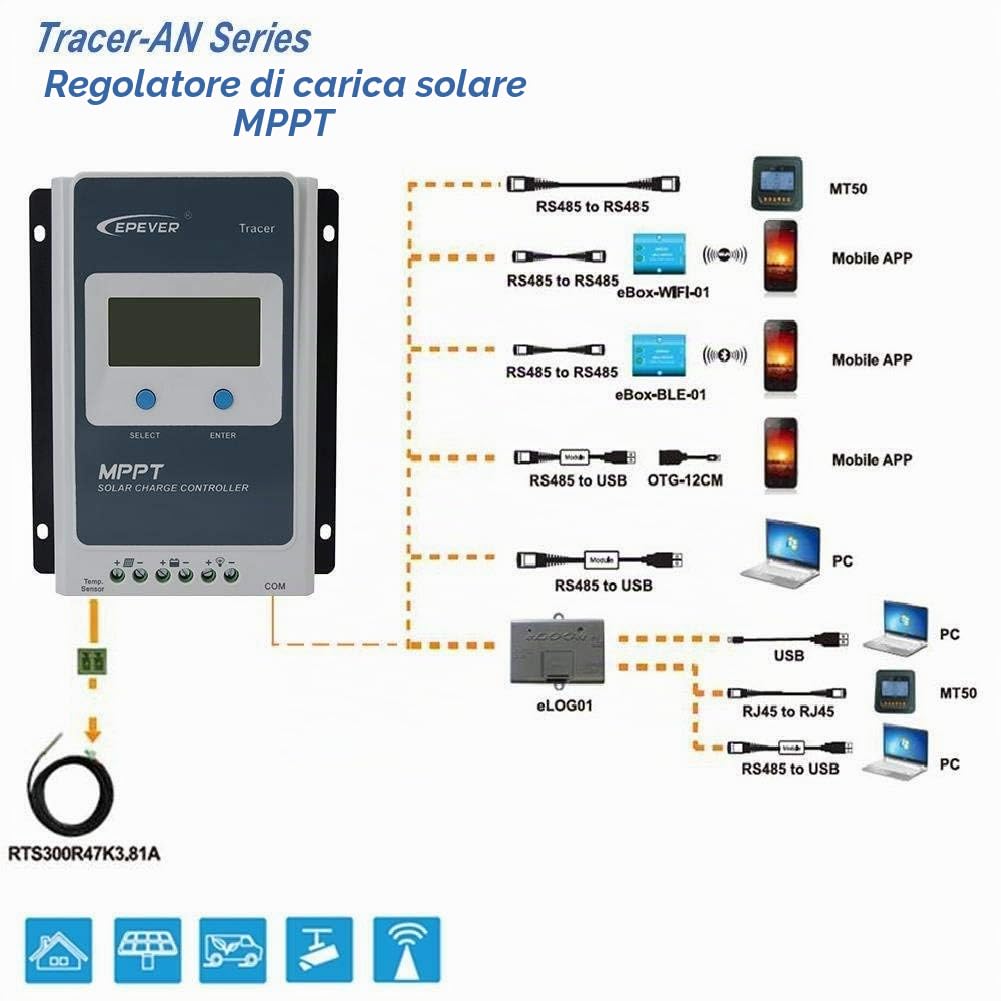
Figure 6: Connectivity options for monitoring and control, including MT50 and PC software.
7. Maintenance
Regular maintenance ensures the longevity and optimal performance of your controller:
- Cleanliness: Keep the controller clean and free from dust and debris. Use a dry cloth for cleaning.
- Connections: Periodically check all wiring connections for tightness and corrosion. Retighten if necessary.
- Ventilation: Ensure that the ventilation openings are not blocked.
- Environmental Check: Verify that the operating environment remains within the specified temperature and humidity ranges.
- Firmware Updates: Check the EPEVER website for any available firmware updates to improve performance or add features.
8. Troubleshooting
If you encounter issues with your controller, refer to the following common problems and solutions:
| Problem | Possible Cause | Solution |
|---|---|---|
| No display on LCD | Battery not connected or low voltage; reverse polarity. | Check battery connections and voltage. Ensure correct polarity. |
| Battery not charging | PV array not connected; low PV voltage; PV reverse polarity; faulty PV module. | Check PV connections and voltage. Verify PV polarity. Inspect PV modules. |
| Load not working | Load disconnected; overload; short circuit; low battery voltage. | Check load connections. Reduce load. Check for short circuits. Charge battery. |
| Controller overheating | Poor ventilation; excessive ambient temperature; overload. | Ensure adequate ventilation. Relocate controller if ambient temperature is too high. Reduce load. |
For more detailed troubleshooting or persistent issues, please consult the comprehensive user manual or contact EPEVER customer support.
9. Specifications
Technical specifications for the EPEVER Tracer2210AN MPPT Solar Charge Controller:
| Parameter | Value |
|---|---|
| Model | Tracer2210AN |
| Rated Charge Current | 20A |
| System Nominal Voltage | 12V / 24V DC Auto Identification |
| Battery Input Voltage Range | 8V - 32V |
| Max. PV Input Power (12V) | 260W |
| Max. PV Input Power (24V) | 520W |
| Max. PV Open Circuit Voltage | 100V |
| Grounding | Common Negative |
| Dimensions (L x W x H) | 15.4 cm x 22 cm x 5.2 cm |
| Item Weight | 1.11 kg |
| Display Type | LCD |
| Operating Temperature | Up to 45°C |
| UPC | 712022186463 |

Figure 7: Physical dimensions and weight of the controller.
10. Warranty and Support
EPEVER products are designed for reliability and performance. For warranty information, please refer to the warranty card included with your product or visit the official EPEVER website.
For technical support, troubleshooting assistance beyond this manual, or inquiries about spare parts, please contact EPEVER customer service through their official channels. Provide your product model (Tracer2210AN) and serial number when seeking support.