
1. Introduction
This manual provides essential information for the safe and effective use of your EUDAX Rectangular DC Motor Kit. Please read all instructions carefully before assembly and operation to ensure proper function and prevent damage or injury.
Safety Warning: This kit contains small parts and is not suitable for children under 3 years due to a choking hazard. Always supervise children during use. Improper wiring can lead to short circuits, causing high temperatures and potential damage to components, including the battery holder.
2. Package Contents
The EUDAX Rectangular DC Motor Kit includes the following components:
- 5 x DC Motors (3V, 24000 RPM) with 9.8 inch (25cm) lead wires
- 5 x 2 x 1.5V AA Battery Holder Cases with 5.12 inch (13cm) wires
- 5 x DC Motor Mounting Bracket Holders
- 5 x 3A/250V 6A/125V 2 Solder Lug SPST On/Off Mini Boat Rocker Switches

Image 2.1: Overview of the EUDAX Rectangular DC Motor Kit components.
3. Specifications
| Component | Parameter | Value |
|---|---|---|
| DC Motor | Voltage | 1.5V - 3V DC |
| Rated Speed | 24000 RPM | |
| Body Length | 38mm (1.46") | |
| Body Diameter | 27mm (1.06") | |
| Shaft Size (L x D) | 10mm x 2.0mm (0.39" x 0.08") | |
| Mounting Hole Distance (center to center) | 15mm (0.59") | |
| Lead Wire Length | 9.8 inches (25cm) | |
| Battery Holder | Battery Type | 2 x 1.5V AA Batteries |
| Lead Wire Length | 5.12 inches (13cm) | |
| Rocker Switch | Rated Voltage/Current | 3A 250V AC / 6A 125V AC |
| Insulated Resistance | ≥ 100M Ω | |
| Contact Resistance | ≤ 50m Ω | |
| Dielectric Strength | 1500VAC/5S | |
| Endurance | ≥ 10000 Cycles | |
| Ambient Temperature | T 85 | |
| Material | Copper, Iron, Plastic |

Image 3.1: Detailed dimensions of the DC motor.

Image 3.2: Dimensions and electrical specifications for the rocker switch.
4. Setup and Assembly
4.1 Wiring the Circuit
Correct wiring is crucial to prevent short circuits and ensure safe operation. Follow the correct circuit diagram carefully.

Image 4.1: Comparison of correct and short circuit diagrams. Ensure your connections match the 'Correct circuit diagram' to avoid overheating and damage.
Correct Circuit Diagram:
- Connect the positive (+) wire from the battery holder to one terminal of the rocker switch.
- Connect the negative (-) wire from the battery holder directly to one motor terminal.
- Connect the other terminal of the rocker switch to the remaining motor terminal.
This configuration allows the switch to complete or break the circuit, controlling the motor's operation. Avoid connecting both battery terminals directly to the motor without a switch or creating a direct path between positive and negative terminals, as this will cause a short circuit.
4.2 Installing the Motor into the Mounting Bracket
The motor mounting bracket provides stability for your projects.

Image 4.2: Two steps to install the motor into its mounting bracket.
- Step 1: Install the motor vertically into the bracket opening.
- Step 2: Gently press and rotate the motor until it securely snaps into place within the bracket.
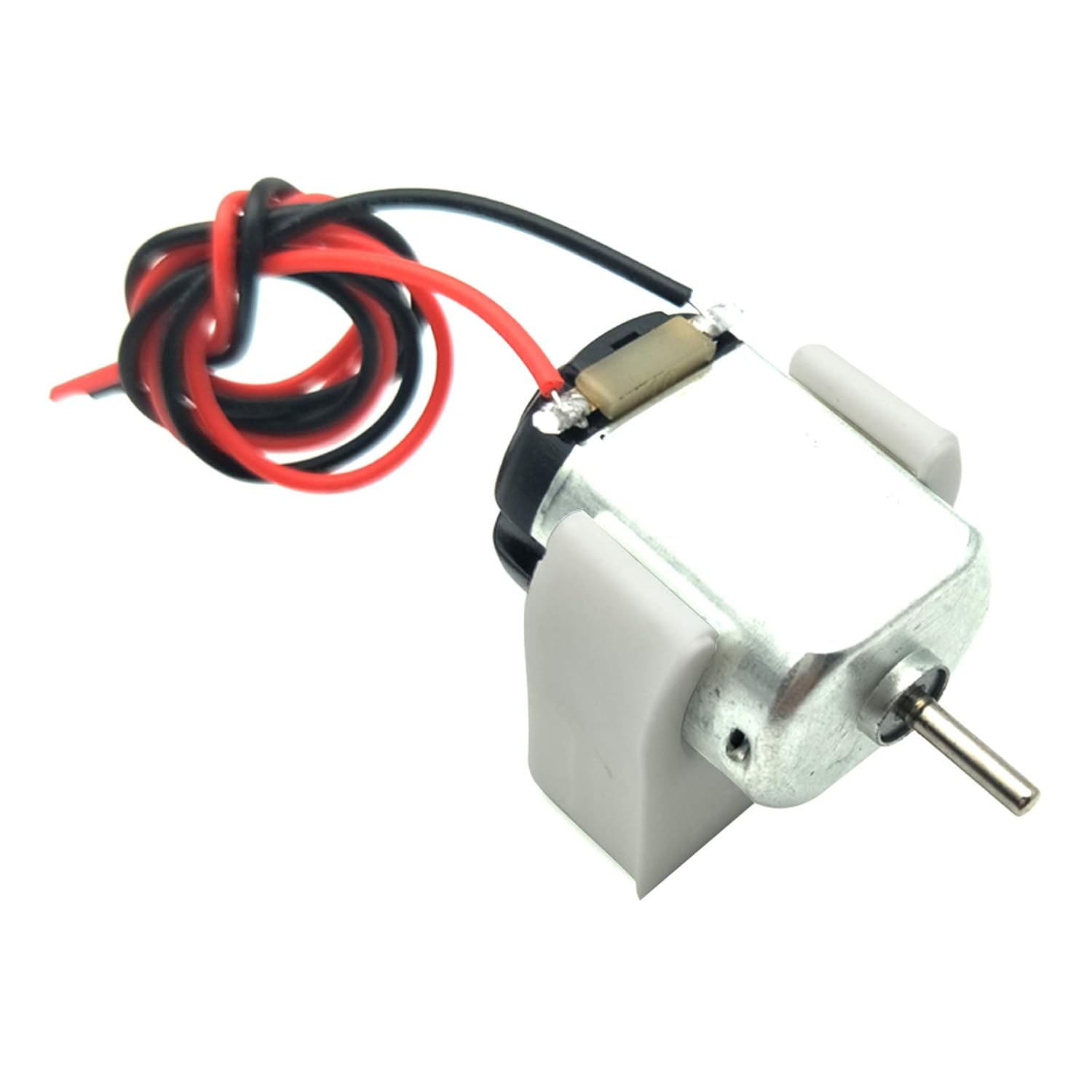
Image 4.3: Side view of the DC motor securely mounted in its bracket.

Image 4.4: Front view of the DC motor securely mounted in its bracket.
4.3 Battery Holder Versions
Your kit may include one of two versions of the AA battery holder. Both function identically.

Image 4.5: Depiction of the 'Old Version' and 'New Version' AA battery holders. Both are functionally equivalent.
5. Operating Instructions
5.1 Powering On/Off
Once the circuit is correctly wired and batteries are inserted into the holder, use the rocker switch to control the motor. Flipping the switch to the 'ON' position will complete the circuit and start the motor. Flipping it to the 'OFF' position will break the circuit and stop the motor.
5.2 Motor Direction
The direction of motor rotation (clockwise or counter-clockwise) depends on the polarity of the power supply connected to the motor terminals. To reverse the motor's direction, simply reverse the positive and negative wire connections to the motor terminals.
6. Maintenance
- Keep components clean and free from dust and debris.
- Store the kit in a dry environment to prevent corrosion.
- Regularly inspect wires for fraying or damage. Replace damaged wires immediately.
- Ensure battery contacts are clean for optimal performance.
7. Troubleshooting
7.1 Motor Not Spinning
- Check Battery Installation: Ensure AA batteries are correctly inserted with the correct polarity in the battery holder.
- Verify Connections: Double-check all wire connections according to the correct circuit diagram (refer to Image 4.1). Loose or incorrect connections will prevent the motor from operating.
- Test Batteries: Ensure batteries have sufficient charge. Replace with fresh batteries if necessary.
- Inspect Switch: Confirm the rocker switch is in the 'ON' position and functioning correctly.
7.2 Overheating Components
- Immediate Disconnection: If any component, especially the battery holder, becomes hot, immediately disconnect the power source (remove batteries or switch off).
- Check for Short Circuits: Overheating is a strong indicator of a short circuit. Carefully review your wiring against the correct circuit diagram (Image 4.1) to identify and correct any improper connections.
- Avoid Prolonged Use: While the motors are designed for various projects, prolonged continuous operation, especially under heavy load, can generate heat. Allow components to cool down between uses.
8. Safety Information
- Choking Hazard: Small parts. Not for children under 3 years. Adult supervision is required for younger users.
- Electrical Safety: Always ensure correct wiring to prevent short circuits. Short circuits can cause high temperatures, melting of plastic components, and potential burns.
- Battery Handling: Use appropriate batteries (AA 1.5V). Do not mix old and new batteries or different types of batteries. Dispose of used batteries responsibly.
- Operating Environment: Use the kit in a dry, well-ventilated area. Avoid contact with water or other liquids.
9. Warranty and Support
For warranty information or technical support, please refer to the product packaging or contact EUDAX customer service through the retailer where the product was purchased. Keep your purchase receipt for proof of purchase.