1. Introduction
This manual provides essential instructions for the proper installation, operation, and maintenance of your Cisa 11931.70.3 Electric Rim Lock. Please read this manual thoroughly before installation and keep it for future reference. This electric rim lock is designed for secure access control applications, offering reliable performance when installed and maintained correctly.
2. Safety Information
- Always disconnect power before performing any installation or maintenance procedures.
- Ensure all electrical connections are made by a qualified professional and comply with local electrical codes.
- Do not attempt to modify the lock's internal components. Unauthorized modifications can void the warranty and compromise security.
- Keep children away from the installation area and ensure small parts are not accessible.
- Use only original Cisa replacement parts if any components need to be replaced.
3. Package Contents
Verify that all items are present and undamaged before proceeding with installation:
- Cisa 11931.70.3 Electric Rim Lock unit
- External cylinder (if included in specific model variant)
- Fixing screws and hardware
- Strike plate
- Keys (if applicable)
- Instruction manual (this document)
4. Product Overview and Dimensions
The Cisa 11931.70.3 is an electric rim lock designed for surface mounting on doors. It features a robust metal construction and is suitable for various security applications. Below is a technical drawing illustrating the lock's dimensions and key components.
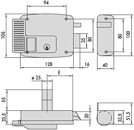
Figure 1: Technical drawing showing the dimensions of the Cisa 11931.70.3 electric rim lock. Key measurements include overall width (94mm), height (106mm), depth (40mm), and bolt projection. All dimensions are in millimeters.
Familiarize yourself with the lock's physical characteristics and dimensions to ensure proper fit and installation on your door. The drawing provides critical measurements for mounting and alignment.
5. Door Handing and Orientation
Correctly identifying the door's handing (left or right, inward or outward opening) is crucial for proper installation and function of the electric rim lock. Refer to the diagram below to determine the appropriate handing for your door.
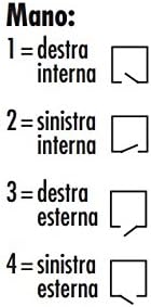
Figure 2: Door handing guide. 1 = Right Internal, 2 = Left Internal, 3 = Right External, 4 = Left External. This diagram helps determine the correct orientation for the lock's installation based on how the door opens and from which side it is viewed.
- Right Internal: Door opens inwards, hinges on the right when viewed from the inside.
- Left Internal: Door opens inwards, hinges on the left when viewed from the inside.
- Right External: Door opens outwards, hinges on the right when viewed from the outside.
- Left External: Door opens outwards, hinges on the left when viewed from the outside.
6. Setup and Installation
Installation should be performed by a competent individual. Ensure all safety precautions are followed.
- Prepare the Door: Mark the desired position for the lock body on the door. Ensure it is at a comfortable height and allows for proper clearance.
- Drill Mounting Holes: Using the provided template (if applicable) or the dimensions from Figure 1, drill pilot holes for the lock body and the external cylinder (if used). Ensure holes are straight and of the correct diameter.
- Install External Cylinder: If your model includes an external cylinder, insert it through the door and secure it according to its specific instructions.
- Mount Lock Body: Position the main lock body on the door, aligning it with the drilled holes. Secure it firmly with the provided screws. Do not overtighten.
- Install Strike Plate: Close the door and mark the position for the strike plate on the door frame, ensuring it aligns perfectly with the lock's bolt. Mount the strike plate securely.
- Electrical Connection: Connect the lock to the power supply and access control system (if applicable) according to the wiring diagram provided with your specific model. Ensure correct polarity and voltage. This step must be performed by a qualified electrician.
- Test Functionality: Before fully securing all covers, test the lock's operation with both the key and the electrical impulse. Ensure the bolt extends and retracts smoothly and the door latches correctly.
7. Operating Instructions
- Manual Operation (Key): Insert the key into the external cylinder and turn it to unlock or lock the door.
- Electric Operation: When an electrical impulse is applied (e.g., from an intercom or access control system), the lock's bolt will retract, allowing the door to be opened. The lock will automatically re-engage when the door is closed, or the impulse is removed, depending on the specific wiring configuration.
- Internal Button/Lever: If your model includes an internal button or lever, it can be used to open the door from the inside without a key or electrical impulse.
8. Maintenance
- Cleaning: Clean the exterior of the lock with a soft, damp cloth. Avoid abrasive cleaners or solvents that could damage the finish.
- Lubrication: Periodically apply a small amount of graphite-based lubricant to the keyway and moving parts of the bolt mechanism to ensure smooth operation. Do not use oil-based lubricants, as they can attract dust and grime.
- Inspection: Regularly check all mounting screws for tightness. Inspect the strike plate for wear and ensure it is securely fastened.
- Electrical Connections: Periodically inspect electrical connections for any signs of wear or corrosion. Ensure they remain secure.
9. Troubleshooting
Refer to the table below for common issues and their potential solutions.
| Problem | Possible Cause | Solution |
|---|---|---|
| Lock does not engage/disengage electrically. | No power, incorrect wiring, faulty solenoid. | Check power supply. Verify wiring connections. Consult a qualified electrician if the solenoid is suspected to be faulty. |
| Key turns but door does not unlock. | Misalignment, worn cylinder, internal mechanism issue. | Check door and frame alignment. Lubricate keyway. If issue persists, professional inspection may be required. |
| Door rattles when closed. | Loose strike plate, worn bolt. | Tighten strike plate screws. Adjust strike plate position if necessary. |
| Lock is stiff or difficult to operate. | Lack of lubrication, dirt/debris. | Clean and lubricate the lock mechanism and keyway. |
If you encounter problems not listed here or if the suggested solutions do not resolve the issue, please contact customer support.
10. Specifications
| Feature | Detail |
|---|---|
| Model Number | 11931.70.3 |
| Brand | Cisa |
| Material | Metal |
| Item Weight | 1.5 Kilograms |
| Number of Pieces | 1 |
| International Article Code (EAN) | 08015345073178 |
| First Available Date | May 18, 2017 |
11. Warranty Information
Cisa products are manufactured to high-quality standards. This product is covered by a manufacturer's warranty against defects in materials and workmanship under normal use. The specific terms and duration of the warranty may vary by region and purchase date. Please retain your proof of purchase for warranty claims. For detailed warranty information, refer to the documentation provided at the time of purchase or visit the official Cisa website.
12. Customer Support
If you require assistance with installation, operation, or troubleshooting that is not covered in this manual, please contact Cisa customer support or your authorized dealer. Have your product model number (11931.70.3) and purchase details ready when contacting support.
- Website: www.cisa.com (Please check for regional websites)
- Contact Information: Refer to the "Contact Us" section on the official Cisa website for phone numbers and email addresses specific to your region.


