1. Introduction
The Juried Engineering UA723CN is a versatile adjustable voltage regulator integrated circuit, designed for a broad range of series regulator applications. This IC is a direct replacement for the LM723CN and LM723, offering reliable performance for various electronic projects. It is capable of supplying output currents up to 150 mA independently, with the flexibility to extend current capabilities beyond 10A by incorporating external pass transistors. The UA723CN features low standby current drain and includes provisions for both linear and foldback current limiting. Its adaptability also allows for use in shunt regulator, current regulator, or temperature controller configurations.
2. Key Features
- Output Current: Up to 151 mA without external pass transistor.
- Extended Output Current: Possible to achieve output currents exceeding 10A with the addition of external transistors.
- Input Voltage Range: Maximum input voltage of 40V.
- Adjustable Output Voltage: Output voltage can be adjusted from 2V to 37V.
- Operating Modes: Can function as either a linear or a switching regulator.
3. Specifications
| Specification | Value |
|---|---|
| Model Number | UA723CN |
| Manufacturer | STMicroelectronics |
| Package Type | DIP-14 |
| Input Voltage (Max) | 40V |
| Output Voltage Range | 2V to 37V |
| Output Current (Internal) | 151 mA |
4. Setup and Pin Configuration
The UA723CN is provided in a DIP-14 package, making it suitable for breadboard prototyping and through-hole PCB mounting. Proper pin identification and connection are crucial for correct operation.

Figure 1: Top view of the UA723CN IC, displaying its markings and package type.
Refer to the official datasheet for the complete pinout diagram and detailed functional descriptions of each pin. Key pins typically include:
- VIN: Input voltage supply.
- VOUT: Regulated output voltage.
- VREF: Internal voltage reference.
- Compensation: Pins for external compensation components.
- Current Limit: Pins for setting current limiting.
- Ground: Common ground connection.
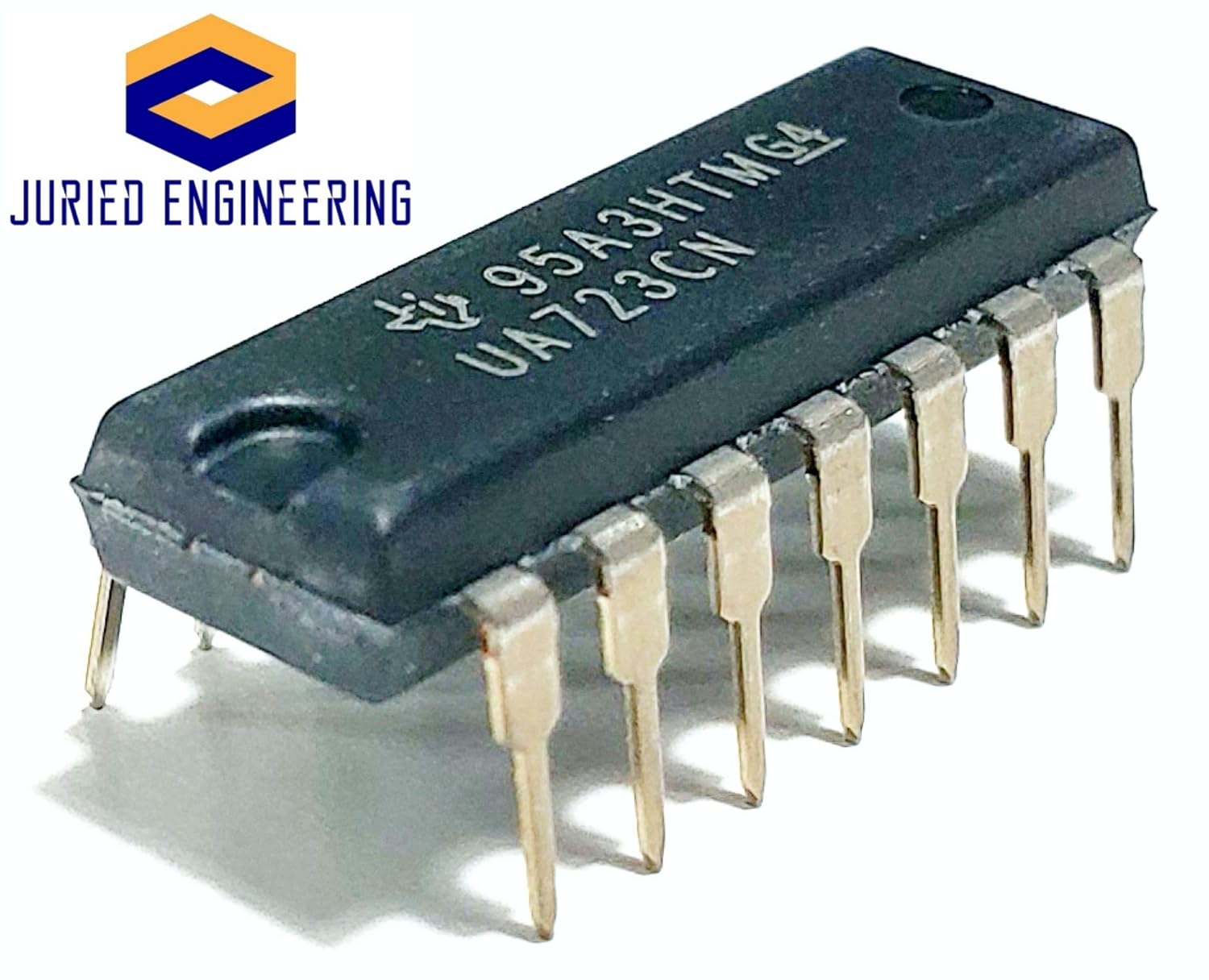
Figure 2: Side view of the UA723CN IC, illustrating the DIP-14 pin configuration.
When integrating the UA723CN into a circuit, ensure proper power supply decoupling and observe polarity for all connections. Use appropriate soldering techniques to avoid damage to the IC or surrounding components.
5. Operating Principles
The UA723CN operates by comparing a fraction of the output voltage to an internal precision voltage reference. Any deviation from the desired output voltage is amplified and used to control a series pass element (internal or external), thereby maintaining a constant output voltage despite variations in input voltage or load current.

Figure 3: Angled view of the UA723CN IC, showing its physical dimensions and pin arrangement.
To adjust the output voltage, external resistors are typically used in a feedback network connected to the IC's error amplifier inputs. Current limiting can be implemented using an external sense resistor to protect the regulator and load from excessive current.
For applications requiring higher output currents, external power transistors can be added to the circuit. The UA723CN then drives these external transistors, allowing for regulation of much larger load currents while maintaining its precise control.
6. Maintenance
Integrated circuits like the UA723CN are generally maintenance-free once properly installed. However, to ensure long-term reliability:
- Environmental Conditions: Operate the IC within its specified temperature and humidity ranges.
- Heat Dissipation: For applications with significant current draw, ensure adequate heat sinking for any external pass transistors and consider the thermal environment of the IC itself.
- Cleanliness: Keep the circuit board free from dust and debris, which can affect performance or lead to short circuits.
- Power Supply Stability: Provide a stable and clean input power supply to prevent stress on the regulator.
7. Troubleshooting
If the UA723CN circuit is not functioning as expected, consider the following troubleshooting steps:
- No Output Voltage:
- Verify input voltage (VIN) is present and within the specified range.
- Check all pin connections for continuity and correct polarity.
- Ensure the IC is correctly oriented in its socket or on the PCB.
- Incorrect Output Voltage:
- Inspect the feedback resistor network for correct values and connections.
- Check for any short circuits or open circuits in the feedback path.
- Measure the internal reference voltage (VREF) if accessible, to ensure it is stable.
- Output Voltage Fluctuations/Instability:
- Check for proper compensation capacitor values and placement.
- Ensure adequate decoupling capacitors are used on the input and output.
- Verify the load is not drawing excessive current, potentially triggering current limiting or thermal shutdown.
- Excessive Heat:
- Confirm that the input-to-output voltage differential is not too high for the current being drawn, leading to excessive power dissipation.
- Ensure any external pass transistors have appropriate heat sinks.
Always disconnect power before making any physical changes to the circuit.
8. Warranty and Support
For specific warranty information and technical support regarding the Juried Engineering UA723CN, please refer to the documentation provided at the point of purchase or contact Juried Engineering directly through their official channels. General product information and datasheets for the UA723CN (or its equivalent LM723) can often be found on the manufacturer's website (STMicroelectronics) or reputable electronic component distributors.


