
CNC4PC C25
CNC4PC C25 Ethernet Smooth Stepper Terminal Board User Manual
Model: C25
1. Introduction
This manual provides detailed instructions for the installation, operation, and maintenance of the CNC4PC C25 Ethernet Smooth Stepper Terminal Board. The C25 board is designed to interface with a Smooth Stepper (from Warp9) to expand its input and output capabilities for CNC applications.
2. Key Features
- Provides 34 Inputs and Outputs across 2 ports.
- Offers full access to all pins of the Smooth Stepper Board.
- Connects directly to the Smooth Stepper (from Warp9) via integrated sockets, eliminating the need for ribbon cables.
- Draws power directly from the Smooth Stepper board, removing the requirement for an additional power supply.
- Includes built-in Passive Low Pass Filters for all inputs to reduce noise from drivers or other devices.
- Operates with TTL 5VDC signals, ensuring compatibility with common automation devices and parallel port interface products.
3. Setup and Installation
The C25 Terminal Board is designed for straightforward integration with your Smooth Stepper unit.
3.1. Connecting the C25 Board
The C25 board features integrated sockets that allow it to plug directly onto the Smooth Stepper board. Align the connectors carefully and press firmly to ensure a secure connection. No ribbon cables are required for this primary connection.
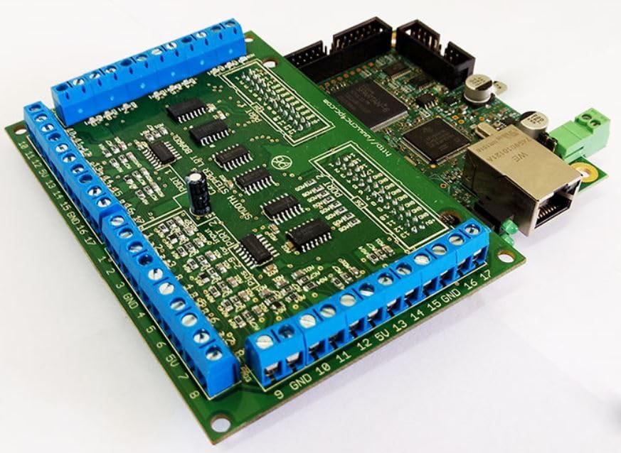
Figure 1: The C25 Terminal Board (green board with blue screw terminals) connected to a Smooth Stepper unit (brown board with Ethernet port).
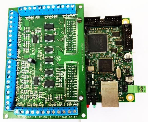
Figure 2: Top view illustrating the direct connection of the C25 Terminal Board to the Smooth Stepper, showing the integrated sockets.
3.2. Power Supply
The C25 board is designed to draw its operational power directly from the connected Smooth Stepper board. An additional external power supply for the C25 board is not required.
3.3. Input/Output Connections
The board provides 34 input and output connections distributed across two ports. These connections are accessible via the blue screw terminals located along the edges of the board. Refer to the silkscreen labels on the board for specific pin assignments (e.g., GND, 5V, 1-17 for Port 1 and Port 2).

Figure 3: Overview of the C25 Terminal Board, highlighting the blue screw terminals for I/O connections.

Figure 4: Angled view of the C25 board, showing the arrangement of screw terminals and board components.
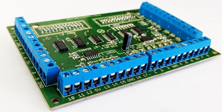
Figure 5: Side perspective of the C25 board, detailing the screw terminal blocks.
All signals on the C25 board are TTL 5VDC, ensuring compatibility with standard automation components. The built-in passive low pass filters on all inputs help to mitigate electrical noise, providing more stable signal integrity.
4. Operating Instructions
Once the C25 Terminal Board is securely connected to the Smooth Stepper and your external devices (motors, sensors, etc.) are wired to the appropriate screw terminals, the system is ready for operation. The C25 acts as an interface, extending the I/O capabilities of the Smooth Stepper. Configuration of the specific I/O functions (e.g., assigning pins to specific machine functions) is typically performed within the software controlling your Smooth Stepper (e.g., Mach3, Mach4).
Consult the documentation for your Smooth Stepper and CNC control software for detailed instructions on configuring and utilizing the extended I/O provided by the C25 board.
5. Maintenance
The C25 Ethernet Smooth Stepper Terminal Board is designed for reliable operation with minimal maintenance. To ensure longevity and proper function:
- Keep the board clean and free from dust, debris, and moisture.
- Ensure all screw terminal connections are secure to prevent intermittent signals or shorts.
- Avoid exposing the board to extreme temperatures or humidity.
- Periodically inspect for any signs of physical damage or loose components.
6. Troubleshooting
If you encounter issues with your C25 Terminal Board, consider the following troubleshooting steps:
- No Power/Activity: Verify that the Smooth Stepper board is powered on and functioning correctly, as the C25 draws power from it.
- Intermittent Signals: Check all screw terminal connections for tightness and proper wiring. Ensure cables are not damaged.
- Unexpected Behavior: Review your CNC control software configuration to ensure that the I/O pins are correctly assigned and configured.
- Noise Issues: While the board has built-in filters, excessive electrical noise in the environment can still affect signals. Ensure proper grounding of your CNC system and shielded cables where appropriate.
- Compatibility: Confirm that all connected devices operate with TTL 5VDC signals.
For advanced troubleshooting or specific wiring diagrams, it may be necessary to consult the data sheets for individual components or contact CNC4PC support.
7. Specifications
| Feature | Detail |
|---|---|
| Model Name | C25 |
| Brand | CNC4PC |
| Number of Ports | 2 |
| Inputs/Outputs | 34 (total) |
| Signal Type | TTL 5VDC |
| Filtering | Built-in Passive Low Pass Filters for inputs |
| Power Source | Powered by Smooth Stepper board |
| Connection Type | Direct plug-in to Smooth Stepper via sockets |
| Package Dimensions | 9.49 x 5.04 x 1.69 inches |
| Item Weight | 5.47 ounces |
8. Warranty and Support
For information regarding product warranty, please refer to the terms and conditions provided by CNC4PC at the time of purchase or visit their official website. For technical support, inquiries, or assistance with specific applications, please contact CNC4PC directly through their official support channels.
Related documentsC25


Ask a question about this manual
Ask about setup, troubleshooting, compatibility, parts, safety, or missing instructions. Manuals+ will review the question and use this page’s manual context to help answer it.