1. Introduction
This manual provides detailed instructions for the installation, operation, and maintenance of your OBO HANDS Stand-Alone Door Access Control System Kit. This system is designed for secure and convenient access management, supporting up to 1000 users with various access modes.
The system features a built-in RFID reader utilizing contactless RFID transponder technology, ensuring sensitive and quick response times. It can function as a standalone keypad, eliminating the need for a computer connection for basic operations.
2. Package Contents
Please verify that all components listed below are included in your package:
- Access Control Keypad
- 180kg/350lbs Electric Magnetic Lock
- DC12V/3A Power Supply
- Door Exit Button
- 10pcs RFID EM ID Keyfobs/Cards
- Mounting Hardware (screws, anchors, L-bracket for magnetic lock)

Overview of the complete access control system kit, including the keypad, magnetic lock, power supply, exit button, and RFID keyfobs/cards.
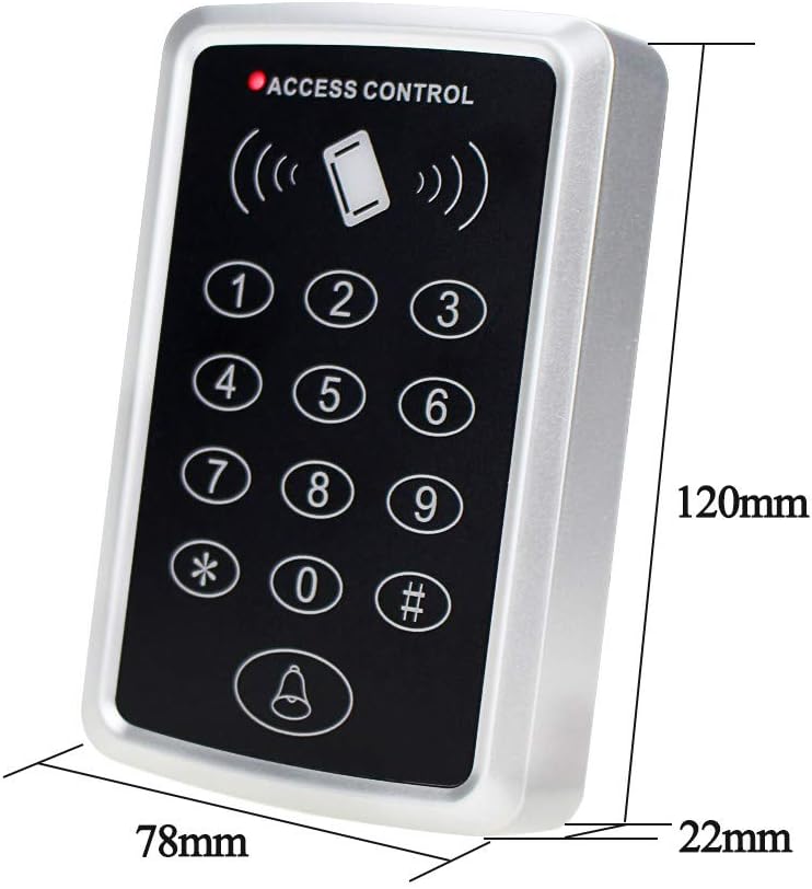
The main access control keypad, showing its compact dimensions of 120mm height, 78mm width, and 22mm depth.

The DC12V/3A power supply control unit, detailing its input (AC110-260V 50-60Hz) and output (DC12V 3A) specifications, along with connection terminals.

The 180kg/350lbs electric magnetic lock, shown with its armature plate and various mounting screws and brackets for installation.
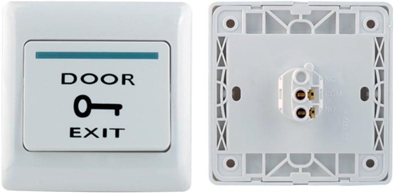
The white door exit button, featuring a key icon and 'DOOR EXIT' text, designed for easy egress from the secured area.

A set of blue RFID keyfobs and white RFID cards, used for contactless access with the control system. These are pre-programmed with unique identities.
3. Setup and Installation
Proper installation is crucial for the optimal performance and security of your access control system. It is recommended that installation be performed by individuals with basic knowledge of access control systems and electrical wiring.
3.1 Wiring Diagram
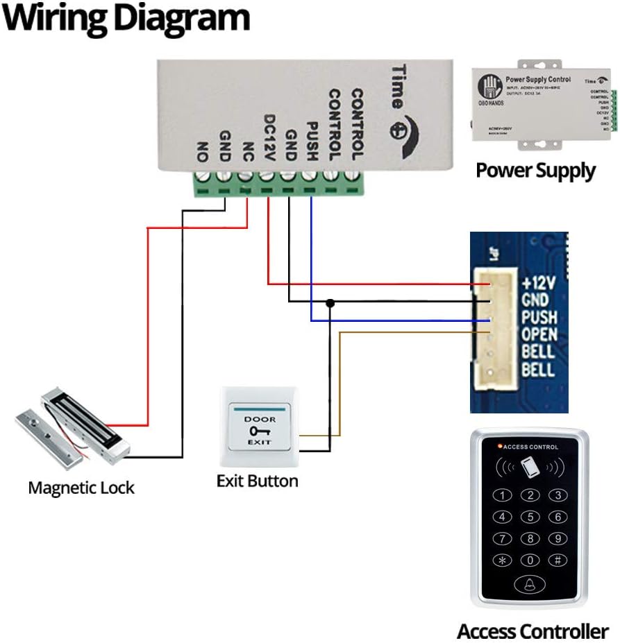
Detailed wiring diagram illustrating the connections between the access controller, power supply, magnetic lock, and exit button. Ensure all connections are secure and follow local electrical codes.
Key Wiring Connections:
- Power Supply to Access Controller: Connect the DC12V output from the power supply to the +12V and GND terminals on the access controller.
- Magnetic Lock Connection: The magnetic lock typically connects to the NC (Normally Closed) and COM (Common) terminals of the power supply or access controller, depending on the desired lock state (fail-safe or fail-secure). Refer to the magnetic lock's specific instructions.
- Exit Button Connection: Connect the exit button to the PUSH and GND terminals on the access controller. Pressing this button will momentarily break the circuit, releasing the lock.
- Door Bell (Optional): If using a doorbell, connect it to the BELL and BELL terminals on the access controller.
3.2 Mounting
Mount the access control keypad, magnetic lock, and power supply in suitable locations. The keypad should be mounted near the entry point, the magnetic lock on the door frame and door, and the power supply in a secure, accessible location. Use the provided mounting hardware and ensure surfaces are clean and dry for self-adhesive components.
4. Operating Instructions
The access control system supports three primary modes for opening the door: RFID card, password, or a combination of card and password.
4.1 Keypad Programming
The following video demonstrates how to program keys and passwords on the keypad. Please follow the steps carefully.
This video tutorial guides you through the process of programming the access control keypad. It covers setting a public password, adding new RFID cards, and modifying the program password for enhanced security. The video shows visual cues for successful and failed operations.
Key Programming Steps (as demonstrated in video):
- Setting Public Password: Use the sequence `# 123456 # 21 7890 #` to set a public password (e.g., 7890).
- Adding Cards: Use `# 123456 # 1 +Card #` to add new RFID cards. Swipe the card after entering the command.
- Deleting Cards: Use `# 123456 # 40 0000 #` to delete all cards.
- Modifying Program Password: Use `# 123456 # 0 456789 # 456789 #` to change the program password (e.g., to 456789).
Note: The default program password is 123456. It is highly recommended to change this immediately after initial setup.
4.2 Access Modes
- RFID Card: Present a programmed RFID card or keyfob to the keypad's reader. The system will verify the card and grant access.
- Password: Enter a valid password on the keypad followed by the '#' key.
- Card + Password: For enhanced security, configure the system to require both a valid RFID card swipe and a correct password entry.
5. Maintenance
To ensure the longevity and reliable operation of your access control system, regular maintenance is recommended:
- Cleaning: Periodically wipe the keypad and magnetic lock surfaces with a soft, dry cloth. Avoid using abrasive cleaners or solvents.
- Cable Inspection: Regularly check all wiring connections for any signs of wear, damage, or loose connections.
- Magnetic Lock Alignment: Ensure the magnetic lock and armature plate remain properly aligned for optimal holding force.
- Software/Firmware: While this is a standalone unit, ensure any available updates or programming changes are applied as needed for security or functionality improvements.
6. Troubleshooting
If you encounter issues with your access control system, refer to the following common problems and solutions:
| Problem | Possible Cause | Solution |
|---|---|---|
| System does not power on. | No power supply connected or faulty power supply. | Ensure the DC12V/3A power supply is correctly connected and receiving AC power. Check power supply output with a multimeter. |
| RFID card/password not recognized (Invalid Card/Password). | Card not programmed, incorrect password, or card deleted. | Ensure the card is properly programmed (refer to Section 4.1). Verify the password entered is correct. If cards were deleted, re-add them. |
| Magnetic lock does not engage/disengage. | Incorrect wiring, insufficient power, or lock malfunction. | Review the wiring diagram (Section 3.1) to ensure correct connections. Check power supply voltage. Inspect the lock for physical damage. |
| Exit button does not work. | Incorrect wiring or faulty button. | Verify the exit button is correctly wired to the PUSH and GND terminals. Test the button for continuity. |
| Difficulty with initial setup/programming. | Instructions unclear or complex for first-time users. | Carefully re-read Section 4.1 and watch the provided video tutorial. Ensure each step is followed precisely, including the '#' key after commands. |
7. Specifications
| Feature | Specification |
|---|---|
| Brand | OBO HANDS |
| Model Number | T11 |
| Power Source | DC (12 Volts) |
| Connectivity Technology | Wired |
| Installation Type | Self-Adhesive |
| Control Method | Touch |
| Sensor Technology | RFID |
| User Capacity | 1000 users |
| Magnetic Lock Holding Force | 180kg / 350lbs |
| Product Dimensions (L x W x H) | 7.87 x 7.87 x 7.87 inches |
| Item Weight | 3.54 pounds |
| Country of Origin | China |
8. Warranty and Support
OBO HANDS products undergo rigorous quality testing to ensure reliability and durability. For any questions or concerns regarding your access control system, please contact our support team:
- Whatsapp: +86 177 2255 8183
- Availability: Mon-Sun 24/7
For additional product information and support, visit the OBO HANDS Store on Amazon.


