
ROHN 25SS040
ROHN 25SS040 40' Self-Supporting Tower Instruction Manual
Model: 25SS040
Brand: ROHN
1. Introduction
This manual provides essential information for the proper installation, operation, and maintenance of the ROHN 25SS040 40' Self-Supporting Tower. This tower is designed for various applications requiring a robust and reliable self-supporting structure without the need for guying in standard conditions. Adherence to these instructions is crucial for safety and optimal performance.

Figure 1.1: ROHN 25SS040 40' Self-Supporting Tower assembled.
2. Safety Information
WARNING: Professional installation is required for this tower system. Improper installation can lead to severe injury, death, or property damage.
Always consult with a qualified and experienced professional for the installation of the ROHN 25SS040 tower. Ensure all local building codes and regulations are strictly followed.
- Load and Wind/Ice Ratings: If your installation exceeds the load, wind, or ice ratings specified by ROHN (refer to the Specifications section and attached documents), you must bracket and/or guy your installation. These additional items are not included and must be purchased separately.
- Grounding: Proper grounding is essential for lightning protection and electrical safety. Grounding kits (e.g., ROHN BGK3G) are available for purchase separately and should be installed according to industry standards and local codes.
- Freight Delivery: Tower sections ship via freight. Your delivery location must be able to accept a full-size semi-truck. If a forklift is not available, you will be required to unband the pallet and remove tower sections by hand (average weight is 45 lbs per section). Be prepared for this upon delivery. Liftgate service is not standard and incurs additional charges.
- Anti-Climb Warning: An ACWS Anti-Climb Warning Sign Kit is included. Install this sign prominently to deter unauthorized climbing.
3. Product Overview and Components
The ROHN 25SS040 tower kit includes the following primary components:
- (3) ROHN 25G Standard 10' Sections
- (1) ROHN 25AG2 Standard 9' 9" Top Section
- (1) ROHN SB25G5 5' Short Base for embedment in concrete
- (1) ACWS Anti-Climb Warning Sign Kit
- ROHN 25G Self-Supporting Tower Specifications documentation
Each tower section is constructed with:
- 1-1/4" OD, 16 Gauge legs
- 5/16" OD Solid Bracing
- Completely hot-dipped galvanized after fabrication for corrosion resistance.
- Built on an 11 1/4" equilateral triangle design.
- Double bolted joints for sturdiness and dependability.
The 25AG2 Top Section features a tapered top and an integrated mounting pipe (14 Gauge x 2.24" OD x 2.08" ID) with an overall length of 9'9".

Figure 3.1: Illustration of ROHN 25G tower sections, showing the lattice structure and connection points.
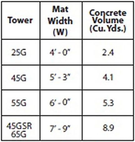
Figure 3.2: Detailed view of a ROHN 25G tower section, highlighting the bracing and leg structure.
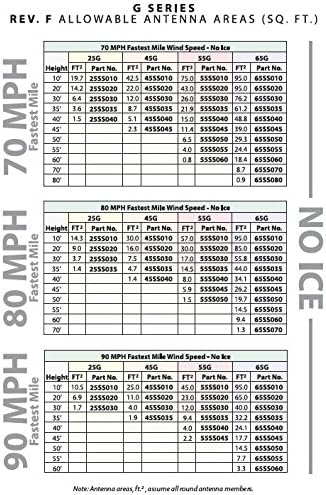
Figure 3.3: Diagram illustrating the equilateral triangle design and key dimensions of the ROHN 25G tower base (11 1/4" equilateral triangle design).
4. Setup and Installation
Installation of the ROHN 25SS040 tower requires specialized knowledge and equipment. It is imperative that installation is performed by qualified professionals.
4.1 Site Preparation
Before installation, ensure the chosen site is suitable for a self-supporting tower. This includes soil analysis, clearance from power lines, and adherence to local zoning laws.
4.2 Foundation Requirements
The ROHN SB25G5 5' Short Base is designed for embedment in concrete. A robust concrete foundation is critical for the stability of the self-supporting tower. Refer to the ROHN 25G Guides for detailed specifications and installation requirements for the foundation.
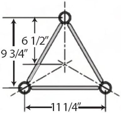
Figure 4.1: Table indicating concrete volume requirements for various ROHN G-series towers, including the 25G.
4.3 Tower Assembly
Tower sections are joined using double bolted joints. Each section is shipped with all required nuts and bolts. The short concrete base can only be connected at one end. The 25AG2 top section integrates a mounting pipe for antennas or other equipment.
Consult the detailed ROHN 25G Guides for step-by-step assembly instructions and torque specifications for all fasteners.
5. Operating Considerations
While the ROHN 25SS040 is a self-supporting tower, its operational limits are defined by its load, wind, and ice ratings. It is crucial to understand and adhere to these limits to ensure the structural integrity and safety of the tower.
5.1 Load Capacity
The tower's capacity to support antennas and other equipment is determined by its design specifications. Do not exceed the maximum allowable antenna area or weight for the specific tower height and wind speed conditions.
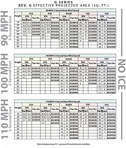
Figure 5.1: Tables detailing ROHN G Series allowable antenna areas (sq. ft.) for various wind speeds (70 MPH, 80 MPH, 90 MPH) with no ice accumulation. This data is critical for determining safe loading.
Figure 5.2: Tables detailing ROHN G Series effective projected area (sq. ft.) for various wind gust speeds (90 MPH, 100 MPH, 110 MPH) with no ice accumulation. This data is critical for determining safe loading under gust conditions.
5.2 Wind and Ice Conditions
The "No Ice" designation for this model indicates its performance under conditions without ice accumulation. In regions prone to ice, additional structural analysis and potential guying or bracing may be necessary. Always refer to the provided ROHN 25G Self-Supporting Tower Specifications for detailed wind and ice load charts relevant to your specific installation environment.
6. Maintenance
Regular inspection and maintenance are vital to ensure the long-term safety and performance of your ROHN 25SS040 tower.
- Visual Inspection: Periodically inspect the entire tower structure for any signs of corrosion, loose bolts, bent members, or damage. Pay close attention to welded joints and connection points.
- Fastener Check: Verify that all nuts and bolts remain securely tightened to the manufacturer's specified torque.
- Grounding System: Inspect the grounding system for corrosion or damage to connections and conductors. Ensure continuity to earth ground.
- Foundation: Check the concrete foundation for cracks, settling, or erosion around the base.
- Galvanization: The tower is hot-dipped galvanized. If any areas show signs of significant rust or damage to the galvanization, consult a professional for repair or recoating.
- Anti-Climb Sign: Ensure the Anti-Climb Warning Sign is visible and intact.
Frequency of inspection should be increased after severe weather events (e.g., high winds, heavy ice storms).
7. Troubleshooting
This section addresses common concerns and potential issues related to tower performance.
- Tower Sway/Vibration:
- Cause: Exceeding load/wind ratings, loose connections, inadequate foundation.
- Solution: Review antenna loading against specifications. Inspect all bolted connections for proper torque. Consult a structural engineer to assess foundation integrity and determine if guying or bracing is required.
- Corrosion/Rust:
- Cause: Damage to galvanization, exposure to harsh environments.
- Solution: Minor surface rust on galvanized steel is common and usually not a structural concern. For significant rust or damage to the protective coating, consult a professional for appropriate repair methods to prevent further degradation.
- Difficulty during Freight Delivery:
- Cause: Lack of appropriate unloading equipment (forklift) or insufficient personnel.
- Solution: Ensure you have the necessary equipment or sufficient manual labor available at the time of delivery. Coordinate with the freight company regarding liftgate service if required (additional charges apply).
For any issues not covered here, or if you suspect structural compromise, immediately cease any work on or near the tower and contact a qualified professional or ROHN customer support.
8. Specifications
| Attribute | Detail |
|---|---|
| Model Number | 25SS040 |
| Brand | ROHN |
| Tower Height | 40 feet |
| Type | Self-Supporting Tower |
| Ice Rating | No Ice |
| Material | Alloy Steel, Hot-Dipped Galvanized |
| Legs | 1-1/4" OD, 16 Gauge |
| Bracing | 5/16" OD Solid Bracing |
| Design | 11 1/4" Equilateral Triangle |
| Joints | Double Bolted |
| Weight | Approximately 300 Pounds (total kit) |
| Manufacturer | Rohn Products |
| Specification Met | 90MPH Rev G/70MPH Rev F |
9. Warranty Information
Specific warranty details for the ROHN 25SS040 tower are provided by the manufacturer, Rohn Products. Please refer to the documentation included with your purchase or visit the official ROHN website for the most current warranty terms and conditions. Keep your proof of purchase for warranty claims.
10. Customer Support
For technical assistance, installation guidance, or inquiries regarding your ROHN 25SS040 tower, please contact Rohn Products directly. You may also reach out to the seller, Antenna Parts Outlet, for support related to your purchase.
It is recommended to have your model number (25SS040) and purchase details ready when contacting support.
Ask a question about this manual
Ask about setup, troubleshooting, compatibility, parts, safety, or missing instructions. Manuals+ will review the question and use this page’s manual context to help answer it.