1. Introduction
The SMARTGEN MGC100 Petrol Genset Controller is designed for the manual and remote start and protection of single gensets. This controller provides essential functions including data measurement, alarm indication, and shutdown protection. It features an LED display and button-press operation for precise measurement of various parameters, ensuring effective control and protection of your genset. The MGC100 is suitable for a wide range of small diesel and petrol gensets, offering ease of operation, reliable performance, a compact structure, and simple connections.
2. Key Features
- Cost-effective controller designed for manual and remote start/stop of generators.
- Compatible with 1-3 phase gasoline and diesel gensets.
- Designed for convenient front panel mounting.
- Engineered to withstand cranking dropouts, ensuring reliable operation.
- Includes comprehensive generator protection features, with built-in alarms and warnings for operational safety.
3. Setup and Installation
Proper installation is crucial for the safe and effective operation of your MGC100 controller. Ensure all connections are secure and follow the wiring diagrams carefully.

Figure 3.1: Front Panel Overview. This image displays the front face of the SmartGen MGC100 controller, featuring the LED display, control buttons (Stop/-, Page/✓, Run/+), and alarm indicators for various operational statuses such as low oil pressure, high temperature, and emergency stop.

Figure 3.2: Rear Panel and Terminal Layout. This image shows the back of the MGC100 controller, detailing the numbered terminal connections for various inputs and outputs, including B-, B+, Crank, Fuel, Optional, High Temp, Low Oil Press, EM.STOP, Remote, Aux. Output, Magnetic Pickup, and Gens AC Voltage (N, W, V, U). This diagram is essential for correct wiring.

Figure 3.3: Typical Application Wiring Diagram. This schematic illustrates a standard wiring configuration for the MGC100 controller with a genset and load. It shows connections for B-, B+, Crank, Fuel, Aux. Output, High Temp, Low Oil Pressure, EM Stop, Remote Start, Magnetic Pickup, and AC Voltage inputs (U, V, W, N). A critical note highlights that for petrol gensets, terminal 4 connects to ignition control, while for diesel gensets, terminal 5 shorts to B+ and terminal 4 connects to fuel output.
3.1 Wiring Connections
- Power Supply: Connect DC9.0V to 18.0V continuous power supply to the B+ and B- terminals.
- Crank Output: Connect the crank relay to the designated crank terminal.
- Fuel Output: Connect the fuel relay to the fuel terminal. Note: For petrol gensets, terminal 4 connects to ignition control. For diesel gensets, terminal 5 needs to be shorted with B+, and terminal 4 connects to fuel output.
- Sensor Inputs: Connect high temperature, low oil pressure, and magnetic pickup sensors to their respective terminals.
- Emergency Stop & Remote Start: Wire the emergency stop button and remote start signal to their dedicated terminals.
- AC Voltage Input: Connect the genset's AC voltage (U, V, W, N) to terminals 13-16 for monitoring.
Important Note: Refer to Figure 3.3 for detailed wiring diagrams. Incorrect wiring can damage the controller or the genset. If unsure, consult a qualified technician.
4. Operating Instructions
The MGC100 controller supports both manual and remote operation modes.
4.1 Manual Operation
- Start: Press the Run/+ button to initiate the genset start sequence. The controller will engage the crank and fuel outputs as configured.
- Stop: Press the Stop/- button to shut down the genset.
- Page/View Parameters: Use the Page/✓ button to cycle through various monitored parameters displayed on the LED screen, such as voltage, frequency, and operating hours.
4.2 Remote Operation
The MGC100 can be started and stopped remotely via the dedicated remote start input. When a valid remote start signal is received, the controller will automatically initiate the genset start sequence. Removing the signal will trigger the shutdown sequence.
5. Maintenance
The MGC100 controller is designed for reliable operation with minimal maintenance. However, regular checks can ensure its longevity and performance:
- Visual Inspection: Periodically inspect the controller and its wiring for any signs of damage, loose connections, or corrosion.
- Cleanliness: Keep the controller's surface clean and free from dust and debris. Use a soft, dry cloth for cleaning. Do not use abrasive cleaners or solvents.
- Environmental Conditions: Ensure the operating environment remains within the specified temperature and humidity ranges to prevent damage.
6. Troubleshooting
The MGC100 controller includes built-in diagnostic features to assist with troubleshooting. Alarms and warnings are indicated on the front panel LED display.
Common Issues and Solutions:
- Controller Not Powering On:
- Check the DC power supply (9.0V to 18.0V) to terminals B+ and B-.
- Verify all power connections are secure and free from corrosion.
- Genset Fails to Start:
- Check the fuel supply and ignition system of the genset.
- Verify the crank and fuel output wiring from the controller to the genset.
- Ensure the remote start signal (if used) is correctly applied.
- Check for any active alarm indicators on the controller's display (e.g., low oil pressure, high temperature, emergency stop). Address the underlying issue indicated by the alarm.
- Incorrect Readings on Display:
- Verify the AC voltage input connections (U, V, W, N) are correct and secure.
- Check the magnetic pickup sensor connection and ensure it is properly calibrated for speed sensing.
- Controller Shuts Down Unexpectedly:
- The controller has shutdown protection functions. Check the alarm indicators for the cause (e.g., over-voltage, under-voltage, over-frequency, under-frequency, high temperature, low oil pressure).
- Address the condition that triggered the shutdown.
If the issue persists after following these steps, contact SMARTGEN customer support for further assistance.
7. Specifications
The following table details the technical specifications of the SMARTGEN MGC100 controller:
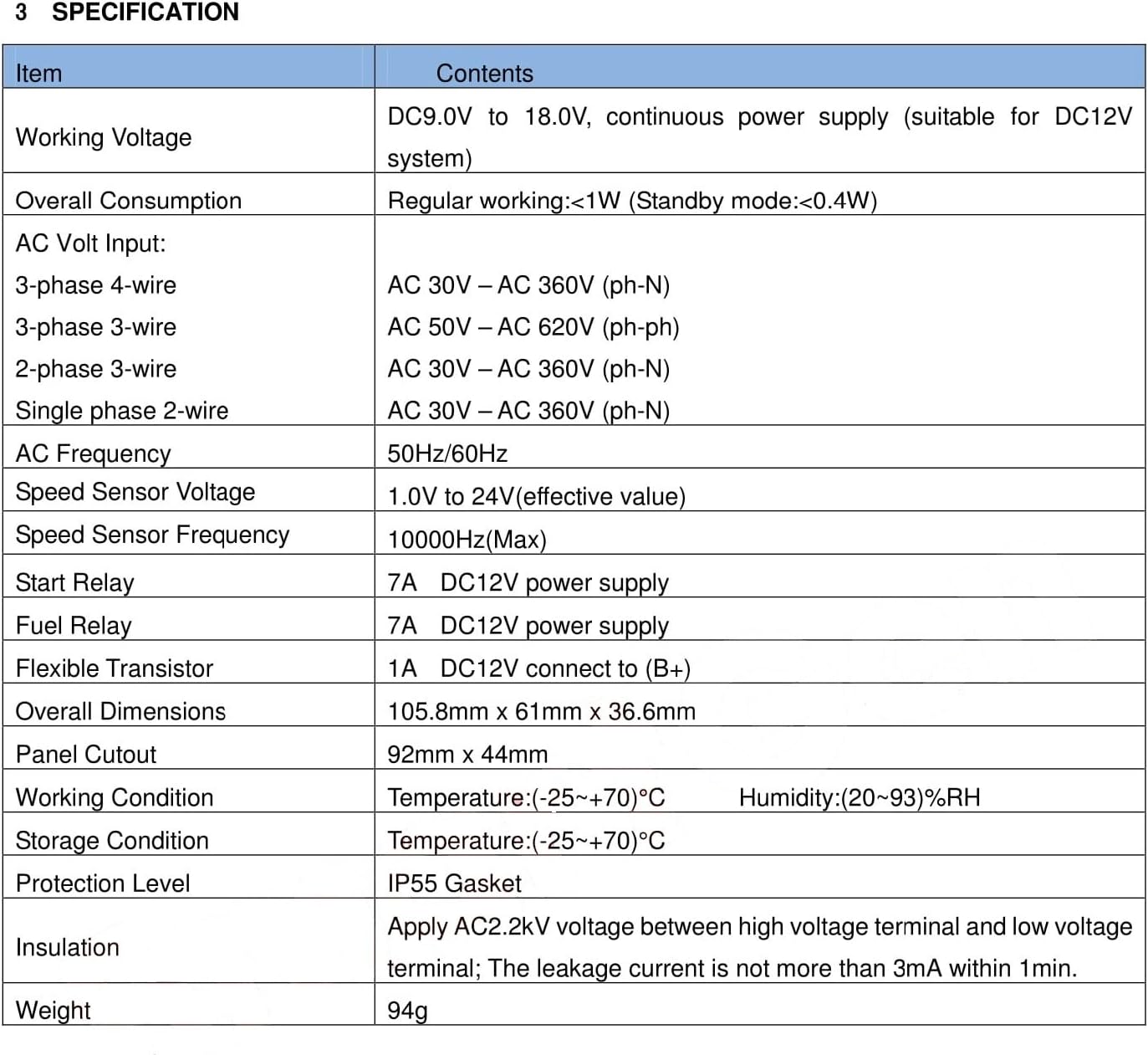
Figure 7.1: MGC100 Specification Table. This image presents a detailed table outlining the electrical, physical, and environmental specifications of the MGC100 controller, including working voltage, power consumption, AC input ranges, relay capacities, dimensions, working conditions, and protection level.
| Item | Specification |
|---|---|
| Working Voltage | DC9.0V to 18.0V, continuous power supply (suitable for DC12V system) |
| Overall Consumption | Regular working:<1W (Standby mode:<0.4W) |
| AC Volt Input (3-phase 4-wire) | AC 30V - AC 360V (ph-ph) |
| AC Volt Input (3-phase 3-wire) | AC 50V - AC 620V (ph-ph) |
| AC Volt Input (2-phase 3-wire) | AC 30V - AC 360V (ph-ph) |
| AC Volt Input (Single phase 2-wire) | AC 30V - AC 360V (ph-N) |
| AC Frequency | 50Hz/60Hz |
| Speed Sensor Voltage | 1.0V to 24V (effective value) |
| Speed Sensor Frequency | 10000Hz (Max) |
| Start Relay | 7A DC12V power supply |
| Fuel Relay | 7A DC12V power supply |
| Flexible Transistor | 1A DC12V connect to (B+) |
| Overall Dimensions | 105.8mm x 61mm x 36.6mm |
| Panel Cutout | 92mm x 44mm |
| Working Condition (Temperature) | (-25~+70)°C |
| Working Condition (Humidity) | (20~93)%RH |
| Storage Condition (Temperature) | (-25~+70)°C |
| Protection Level | IP55 Gasket |
| Insulation | Apply AC2.2kV voltage between high voltage terminal and low voltage terminal; The leakage current is not more than 3mA within 1min. |
| Weight | 94g |
8. Warranty and Support
For warranty information and technical support, please refer to the official SMARTGEN website or contact your authorized dealer. Keep your purchase receipt for warranty claims.
For additional resources and product information, you may visit the product page on Amazon.


