1. Introduction
This manual provides essential information for the safe and efficient installation, operation, and maintenance of the INSTRUKART ABB TTH200 Temperature Transmitter. Please read this manual thoroughly before using the device.
2. Safety Information
Always observe local safety regulations and guidelines when installing, operating, or maintaining the transmitter. Ensure power is disconnected before performing any wiring or maintenance tasks.
- The device must be installed by qualified personnel.
- Verify power supply specifications before connection.
- Avoid exposure to extreme temperatures or corrosive environments beyond specified limits.
3. Product Overview
The ABB TTH200 is a head-mounted temperature transmitter designed for converting various temperature sensor signals into a standardized output signal, typically 4-20 mA with HART communication. Its robust polycarbonate housing ensures durability in industrial environments.

Figure 3.1: Top view of the ABB TTH200 Temperature Transmitter, showing the ABB logo, model number TTH200, HART communication symbol, and CE marking. The label also indicates manufacturing details and IP20 rating.
4. Setup and Installation
4.1 Mounting
The TTH200 is designed for head mounting in standard sensor connection heads. Ensure the mounting location provides adequate ventilation and protection from excessive vibration.
4.2 Wiring Connections
The transmitter accepts various input types. Refer to the internal wiring diagram for correct sensor and power supply connections.

Figure 4.1: Internal view of the ABB TTH200 Temperature Transmitter showing terminal connections and a schematic for 2, 3, and 4-wire sensor configurations. The ABB logo is visible on the left.
- Power Supply: Connect 11-42 VDC to the designated power terminals.
- Sensor Input:
- RTD Pt-100: Connect according to 2, 3, or 4-wire configuration as per the diagram.
- Thermocouples (B, E, J, K, N, R, S, T): Observe polarity for correct connection.
- Voltage/mV Voltage: Connect to the appropriate input terminals.
- Electrical Interface: The device features a 3.5 kV DC (approx. 2.5 kV AC) 60 s isolation between input and output.
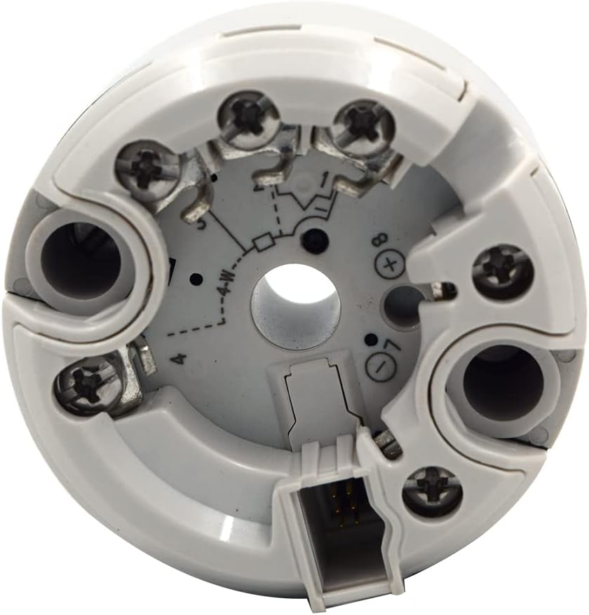
Figure 4.2: Another internal view of the ABB TTH200 Temperature Transmitter, highlighting the terminal screws and the central opening for sensor wiring. This perspective shows the depth of the terminal block.
5. Operating Instructions
5.1 Configuration via HART Protocol
The TTH200 supports HART communication, allowing for remote configuration, monitoring, and diagnostics. A HART communicator or compatible software is required.

Figure 5.1: The ABB TTH200 Temperature Transmitter connected to a smartphone via a cable, demonstrating its HART communication capability for configuration and data display.
- Connect the HART communicator to the transmitter's output loop.
- Use the communicator's interface to set parameters such as sensor type, measurement range, output scaling, and damping.
- Verify the configuration settings before putting the transmitter into service.
5.2 Data Monitoring
Once configured, the transmitter will output a 4-20 mA signal proportional to the measured temperature. The HART protocol also allows for digital access to process variables, device status, and diagnostic information.
6. Maintenance
6.1 Calibration
The transmitter is supplied with a calibration valid for one year, traceable to National Standards. Regular recalibration is recommended to ensure continued accuracy, especially in critical applications.
6.2 Cleaning
Clean the exterior of the transmitter with a soft, damp cloth. Do not use abrasive cleaners or solvents that could damage the polycarbonate housing.
6.3 Storage
If storing the transmitter, ensure it is kept within the specified storage temperature range of -50°C to 85°C (-58°F to 185°F) in a dry environment.
7. Troubleshooting
This section provides general guidance for common issues. For complex problems, contact technical support.
- No Output Signal:
- Check power supply connections and voltage (11-42 VDC).
- Verify sensor wiring and integrity.
- Ensure correct configuration via HART protocol.
- Inaccurate Readings:
- Check sensor type and range settings in the configuration.
- Inspect sensor for damage or incorrect installation.
- Consider recalibration if accuracy drift is suspected.
- HART Communication Failure:
- Ensure HART communicator is properly connected to the loop.
- Verify loop impedance is within HART specifications.
8. Specifications
| Parameter | Value |
|---|---|
| Model | TTH200 |
| Ambient Temperature Standard | -40 … 85 °C (-40 … 185 °F) |
| Storage Temperature | -50°C … 85°C (-58 … 185 °F) |
| Power Supply | 11-42 VDC |
| Electrical Interface Isolation | 3.5 kV DC (approx. 2.5 kV AC) 60 s, input to output |
| Input Types | Resistance RTD Pt-100, Thermocouples B, E, J, K, N, R, S, T, Voltages, mV Voltages |
| Input Resistance | > 10 MΩ |
| Housing Material | Polycarbonate |
| Communication Protocol | HART protocol |
| Vibration Resistance | 10 … 2,000 Hz at 5 g in acc. with IEC 60068-2-6 |
| Manufacturer | ABB |
9. Warranty and Support
9.1 Calibration Warranty
The product includes a calibration certificate valid for one year from the date of purchase, traceable to National Standards. This ensures the initial accuracy of the device.
9.2 Product Support
For technical assistance, troubleshooting beyond this manual, or inquiries regarding the INSTRUKART ABB TTH200 Temperature Transmitter, please contact INSTRUKART customer support. You can find more information on the official INSTRUKART Store.
Note: This item is non-refundable. Please ensure it meets your requirements before purchase.


