
1. Introduction
This manual provides detailed instructions for the installation, operation, and maintenance of the Speedway Motors Universal Watts Link, Model 91649023. This component is designed to enhance the lateral control of your vehicle's rear axle, offering a more precise solution compared to traditional Panhard bars, especially in multi-link suspension setups.
Proper installation and understanding of this system are crucial for optimal performance and safety. Please read this manual thoroughly before beginning any work.
2. Product Overview and Features
The Speedway Motors Universal Watts Link is engineered to provide superior lateral axle control. Key features include:
- Precise Lateral Control: Offers more accurate control of the axle's lateral movement than a Panhard bar setup.
- Suspension Compatibility: Ideal for coil spring or coil-over rear suspensions utilizing parallel suspension links.
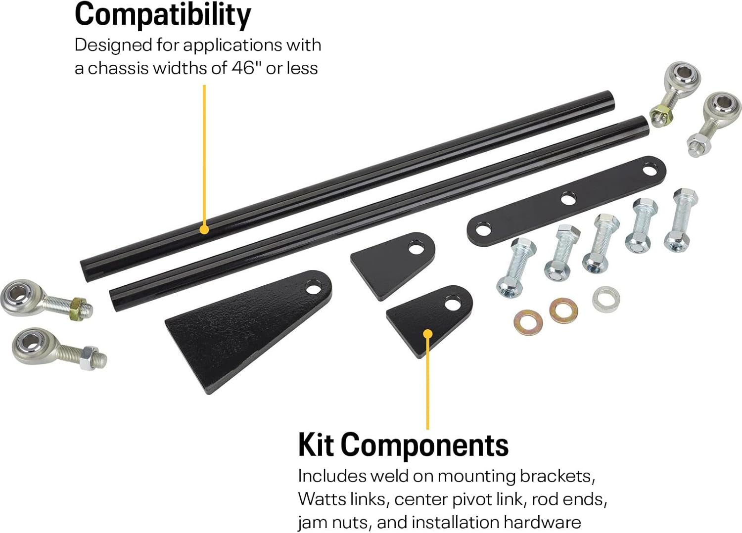
- Chassis Width: Designed for applications with chassis widths of 46 inches or less.
- Adjustable Links: 19-inch long Watts links are threaded 2 inches on each end, allowing for on-vehicle adjustments. Links can be shortened by cutting the left-hand threaded end and re-tapping threads if necessary.
- Durable Construction: Features 19-inch DOM 3/4-inch OD steel links with .180-inch wall thickness.

3. Components List
The Universal Watts Link kit includes the following components:
- Weld-on mounting brackets (3/8-inch thick center pivot bracket, 5/16-inch thick frame tabs)
- Watts links (19-inch DOM 3/4-inch OD steel, .180-inch wall thickness)
- Center pivot link (1/4-inch thick plate steel)
- Left-hand and right-hand threaded 1/2-20 rod ends
- Jam nuts
- Installation hardware (bolts, washers)

4. Setup and Installation
Installation of the Universal Watts Link requires welding and mechanical expertise. If you are not comfortable with these procedures, it is recommended to seek professional assistance.
4.1 Pre-Installation Considerations
- Ensure your chassis width is 46 inches or less for proper fitment.
- Confirm compatibility with your existing coil spring or coil-over rear suspension system.
- Gather all necessary tools, including welding equipment, measuring tools, and safety gear.
4.2 General Installation Steps
- Vehicle Preparation: Safely lift and support the vehicle on jack stands or a lift. Ensure the rear axle is supported independently to allow for movement during installation.
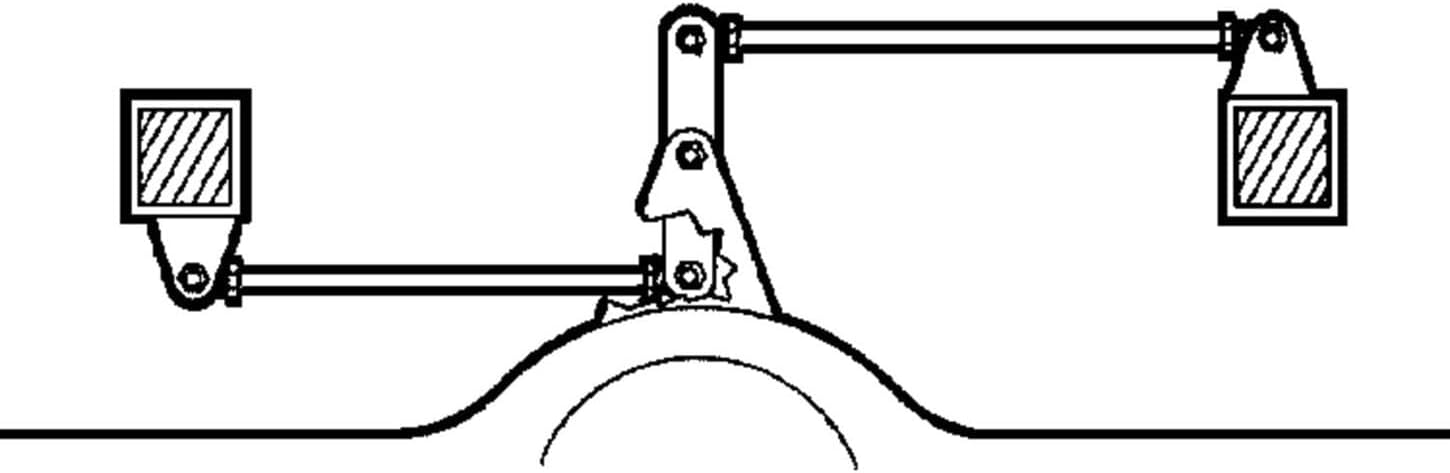
- Component Placement: Determine the optimal mounting locations for the center pivot bracket on the rear axle and the frame tabs on the chassis. The Watts link system typically mounts with the center pivot on the axle and the outer links connecting to the frame.
- Trial Fitment: Temporarily position all components to verify clearances and ensure the Watts links operate freely through the full range of suspension travel. Adjust link lengths using the threaded rod ends as needed. If links require significant shortening, cut the left-hand threaded end and re-tap threads.
- Welding: Securely weld the center pivot bracket to the rear axle and the frame tabs to the chassis. Ensure strong, clean welds for structural integrity. Allow welds to cool completely.
- Final Assembly: Attach the Watts links to the center pivot and frame tabs using the provided rod ends, jam nuts, and hardware. Torque all fasteners to manufacturer specifications (if available, otherwise standard automotive torque for bolt size).
- Inspection: Double-check all connections, welds, and clearances. Ensure no components interfere with other vehicle parts during suspension articulation.
5. Operating Principles
A Watts link system provides superior lateral axle location compared to a Panhard bar. While a Panhard bar moves the axle in an arc, causing slight lateral shift during suspension travel, a Watts link uses a central pivot and two opposing links to keep the axle centered relative to the chassis. This design minimizes lateral movement of the axle, leading to more predictable handling and improved stability, especially during cornering.

6. Maintenance
Regular inspection and maintenance are essential to ensure the longevity and proper function of your Watts Link system:
- Visual Inspection: Periodically check all components for signs of wear, damage, or corrosion. Look for cracks in welds, bent links, or damaged rod ends.
- Fastener Torque: Verify that all bolts and jam nuts are securely tightened to their specified torque values. Loose fasteners can lead to premature wear or failure.
- Rod End Condition: Inspect rod ends for excessive play or binding. Replace worn rod ends promptly to maintain precise control.
- Cleaning: Keep the Watts link components clean from dirt, debris, and corrosive materials.
7. Troubleshooting
If you experience issues after installing the Watts Link, consider the following:
- Excessive Lateral Movement:
- Check for loose rod ends or mounting hardware.
- Inspect rod ends for wear and replace if necessary.
- Verify welds are intact and free from cracks.
- Binding or Restricted Suspension Travel:
- Ensure all components have adequate clearance throughout the full range of suspension travel.
- Check for incorrect link lengths or pivot point alignment.
- Unusual Noises (Clunking, Squeaking):
- Inspect for loose components or contact between the Watts link and other vehicle parts.
- Check rod ends for wear or lack of lubrication (if applicable).
For persistent issues, consult with a qualified automotive technician or contact Speedway Motors customer support.
8. Specifications
| Attribute | Value |
|---|---|
| Model Number | 91649023 |
| Brand | Speedway Motors |
| Item Weight | 8 pounds |
| Product Dimensions | 19.4 x 3.4 x 2.1 inches (packaged) |
| Watts Link Length | 19 inches (nominal) |
| Watts Link Material | DOM 3/4-inch OD steel, .180-inch wall thickness |
| Rod Ends | 1/2-20 threaded (left hand and right hand) |
| Center Pivot Bracket Thickness | 3/8-inch |
| Frame Tab Thickness | 5/16-inch |
9. Warranty and Support
This product is manufactured by Speedway Motors. For specific warranty information, please refer to the official Speedway Motors website or contact their customer service directly. General return policies may apply as per the retailer's terms, typically allowing returns within 30 days of purchase.
For technical assistance, installation guidance, or inquiries regarding parts, please contact Speedway Motors customer support:
- Brand Website: www.speedwaymotors.com
- Customer Service: Refer to the website for contact details.