1. Introduction
This manual provides essential information for the proper installation, operation, and maintenance of the DIXELL XR40CX-4N0C0 Refrigeration Controller. This device is designed for refrigeration applications, offering precise temperature control and management for various commercial and industrial cooling systems.
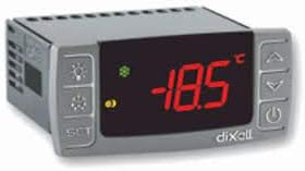
This image displays the front panel of the DIXELL XR40CX-4N0C0 refrigeration controller. It features a red LED digital display, showing a temperature reading of -18.5°C. To the left of the display are three buttons: 'SET', 'Light/Mute', and 'Auxiliary Function'. To the right are three more buttons: 'Up Arrow', 'Down Arrow', and 'Power/Standby'. Small indicator lights are also visible above the display.
2. Safety Information
Please read and understand all safety instructions before installing or operating the controller. Failure to comply may result in personal injury, equipment damage, or voiding of warranty.
- Electrical Safety: This device operates on 110Vac. Installation and maintenance should only be performed by qualified personnel to prevent electrical shock or damage to the unit. Disconnect power before any installation or maintenance procedures. Ensure proper grounding.
- Environmental Conditions: Operate the controller within specified temperature and humidity ranges (0°C to 60°C, 20-85% RH non-condensing). Avoid exposure to water, corrosive substances, or excessive vibrations.
- Intended Use: The XR40CX-4N0C0 is intended for refrigeration control applications. Do not use for purposes other than those specified.
3. Product Overview
The DIXELL XR40CX-4N0C0 is a microprocessor-based controller designed for refrigeration units. It features a 3-digit red LED display, a 6-button keyboard for parameter adjustment, and multiple probe inputs and relay outputs for comprehensive system management.
Key Features:
- Display: 3 digits, decimal point (d.p.)
- Keyboard: 6 push buttons for intuitive control
- Power Supply: 110Vac
- Probe Inputs: Thermostat NTC / PTC, Defrost NTC / PTC, Display NTC / PTC, Condenser NTC / PTC
- Digital Inputs: Configurable for functions such as alarm, start defrost, door switch, pressure switch
- Relay Outputs: Compressor (20A), Defrost (8A), Fans (8A), Light/ON/OFF (8A, 16A optional)
- Other Outputs: Hot Key/Prog Tool Kit output present, Remote display output X-REP (optional), Serial output TTL
4. Specifications
| Parameter | Value |
|---|---|
| Operating Temperature | 0°C to 60°C (32°F to 140°F) |
| Storage Temperature | -30°C to 85°C (-22°F to 185°F) |
| Relative Humidity | 20% to 85% (non-condensing) |
| Power Supply | 110Vac |
| Display Type | Red LED (13mm high) with icons |
| Housing | Self-extinguishing ABS |
| Front Protection | IP65 with gasket |
| Resolution | 0.1°C or 1°F |
| Accuracy | Better than 1% of full scale |
| Connection | Screw-terminal block <2.5mm² and 6.3mm faston |
| Data Storage | EEPROM memory |
5. Installation and Setup
Installation should only be performed by qualified and experienced personnel due to the electrical nature of the device.
5.1 Mounting
The controller is designed for panel mounting. Ensure adequate ventilation around the unit to prevent overheating. Follow the cutout dimensions provided in the product's technical datasheet for proper fit.
5.2 Wiring
All wiring must comply with local electrical codes and regulations. Refer to the wiring diagram provided with the controller for specific terminal connections.
- Power Supply: Connect the 110Vac power supply to the designated power terminals.
- Probes: Connect temperature probes (NTC/PTC) to their respective inputs (Thermostat, Defrost, Display, Condenser). Ensure correct polarity if applicable.
- Loads: Connect loads such as the compressor, defrost heater, fans, and light to the appropriate relay outputs. Ensure the current ratings of the loads do not exceed the relay specifications.
- Digital Inputs: Connect external devices (e.g., door switch, pressure switch) to the configurable digital inputs as required by your application.
5.3 Probe Installation
Install temperature probes in locations representative of the temperature to be controlled or monitored. Ensure probes are securely fastened and protected from mechanical damage and moisture. The thermostat probe should be placed to accurately measure the air or product temperature.
5.4 Initial Power-Up
After all wiring is complete and verified, apply power to the controller. The display should illuminate and typically show the current temperature reading from the thermostat probe. If the display does not light up, immediately disconnect power and check all connections.
6. Operating Instructions
6.1 Display Information
The main display shows the current temperature measured by the thermostat probe. Various icons on the display indicate the operational status of the controller, such as compressor activity, defrost cycle in progress, alarm conditions, or fan operation.
6.2 Setting the Setpoint
To adjust the desired temperature (setpoint):
- Press the 'SET' button. The current setpoint value will begin to flash on the display.
- Use the 'Up Arrow' and 'Down Arrow' buttons to increase or decrease the setpoint value.
- Press 'SET' again to confirm the new setpoint and exit the setting mode. Alternatively, the controller will automatically exit after approximately 10 seconds of inactivity.
6.3 Manual Defrost
To initiate a manual defrost cycle (if configured):
- Press and hold the designated 'Defrost' button (often combined with another function, refer to specific button labels on your unit) for a few seconds until the defrost icon appears or the defrost cycle begins.
6.4 Parameter Programming
Advanced parameters (e.g., hysteresis, defrost intervals, alarm thresholds, probe calibration) are accessible through a specific key combination, typically by holding 'SET' and 'Down Arrow' buttons simultaneously for several seconds. Access to these parameters allows for fine-tuning the controller's operation.
Important Note: Incorrect parameter settings can lead to system malfunction, inefficient operation, or damage to connected equipment. Only adjust these parameters if you fully understand their implications. Refer to the detailed programming manual for a complete list of parameters and their functions.
7. Maintenance
Regular maintenance ensures optimal performance and longevity of your DIXELL XR40CX-4N0C0 controller.
- Cleaning: Clean the front panel of the controller with a soft, damp cloth. Do not use abrasive cleaners, solvents, or excessive liquid, as these can damage the display or internal components.
- Probe Inspection: Periodically inspect all temperature probes for any signs of physical damage, corrosion, or loose connections. Ensure they are securely fastened in their correct positions.
- Terminal Connections: In environments with vibration or significant temperature fluctuations, occasionally inspect the screw-terminal block connections to ensure they remain tight and secure. Loose connections can lead to intermittent operation or electrical hazards.
8. Troubleshooting
This section provides solutions to common issues. For more complex problems, contact technical support.
| Problem | Possible Cause | Solution |
|---|---|---|
| Display Off | No power supply, controller in standby mode, faulty wiring. | Check 110Vac power supply. Verify wiring connections. Press the power button to exit standby mode. |
| Incorrect Temperature Reading | Loose or damaged probe, incorrect probe type setting, probe out of calibration. | Verify probe connections. Check if the probe type (NTC/PTC) matches the controller's configuration. Inspect probes for damage. Calibrate if necessary (refer to programming manual). |
| Compressor Not Starting/Stopping | Setpoint/differential issues, faulty compressor relay, digital input inhibiting operation (e.g., door switch). | Check setpoint and differential settings. Verify compressor relay output. Check status of digital inputs (e.g., door switch, pressure switch) that might inhibit compressor operation. |
| Alarm Indication | High/low temperature, probe error, door open, pressure switch activation. | Identify the alarm code on the display (if applicable) and consult the programming manual for its meaning. Address the underlying cause of the alarm. |
| Unit Not Responding | Software glitch, internal fault. | Disconnect power for a few minutes, then reapply. If the issue persists, contact technical support. |
9. Warranty and Support
For detailed warranty information regarding your DIXELL XR40CX-4N0C0 Refrigeration Controller, please refer to the terms and conditions provided by your point of purchase or the official documentation from the manufacturer, DIXELL, or your distributor, Xiltek. Technical support and service may be available through your seller or the manufacturer's official channels.
It is recommended to keep your purchase receipt and product serial number readily available when contacting support.