1. Introduction
This manual provides detailed instructions for the installation, operation, and maintenance of your NBPOWER 48V/72V 80A Dual Mode Brushless Sine Wave Controller and SW900 Display. This system is designed for electric bicycles and scooters utilizing 3000W to 5000W hub motors. Please read this manual thoroughly before use to ensure proper function and safety.
2. Safety Information
- Always wear appropriate safety gear when operating an electric bicycle or scooter.
- Ensure all connections are secure and properly insulated to prevent short circuits.
- Do not attempt to open or modify the controller or display unit, as this may void the warranty and cause damage.
- Keep the controller and display away from water and extreme temperatures.
- Disconnect the battery before performing any maintenance or installation procedures.
- Consult a qualified technician if you are unsure about any installation steps.
3. Product Overview
The NBPOWER kit includes a high-performance brushless sine wave controller and an SW900 LCD display, designed to provide efficient power management and comprehensive riding data for your electric vehicle.

Figure 3.1: Complete NBPOWER Controller and SW900 Display Kit, including the controller, SW900 display, throttle, and wiring harness.
3.1 Components Included
- 1 x 48V/72V 80A Brushless Motor Controller
- 1 x 48V/72V SW900 Display
- Wiring Harnesses
- Battery Connection Terminal Block
- Storage Bag (optional accessory)

Figure 3.2: The SW900 LCD Display, showing speed, mileage, and error codes.

Figure 3.3: The NBPOWER 80A Brushless Controller unit.

Figure 3.4: Battery connection terminal block with bolts, nuts, and washers.

Figure 3.5: Controller storage bag with dimensions (27cm length, 9.5cm height, 7cm width).
4. Specifications
4.1 Controller Specifications
- Model: NBP-KT-KZQ
- Rated Voltage: DC 48V/72V
- Rated Current: 30A
- Maximum Current: 80 ± 1A
- Speed Set: 1-4.2V Dual Mode Sine Wave
- Brake Input: LOW-LEVEL
- Low Voltage Protection: DC50 ± 0.5V
- Operating Conditions: -40°C to 80°C
- Color: Silver
- Certification: CE
- Application: For Max. 3000W-5000W Hub Motor Electric Bicycle/E-bike Kit
Figure 4.1: Controller dimensions: 215mm length, 100mm width, 56mm height.
4.2 SW900 Display Specifications
- Display Type: LCD
- Functions: Riding speed, single mileage, cumulative mileage, riding time, power-assist gear, motor power and temperature, battery voltage and charge status, brake status, ambient temperature.

Figure 4.2: SW900 Display dimensions: 110mm (approx. 4.33 inches) length, 60mm (approx. 2.36 inches) height. Wire length: 1.65m.
5. Setup and Installation
Careful installation is crucial for the proper functioning and longevity of your e-bike system. Ensure the battery is disconnected before beginning installation.
5.1 Controller Mounting
Mount the controller in a secure location on your bicycle, preferably within the provided storage bag (if applicable) or a similar protective enclosure, away from direct moisture and excessive vibration. Ensure adequate airflow for cooling.
5.2 SW900 Display Mounting
Mount the SW900 display on your handlebars in a position that is easily visible and accessible while riding. Secure it firmly using the provided bracket.
5.3 Wiring Diagram and Connections
Refer to the wiring diagram below for correct connections. Each connector is typically color-coded and uniquely shaped to prevent incorrect connections. Ensure all connections are firm and insulated.
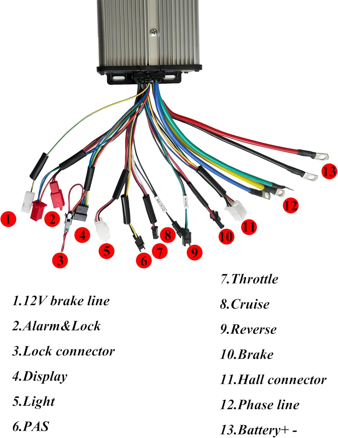
Figure 5.1: Detailed wiring diagram for the NBPOWER controller. Key connections are numbered for identification.
- 12V Brake Line: Connects to the brake lever sensor for motor cut-off.
- Alarm & Lock: For connecting an alarm system and motor lock function.
- Lock Connector: For ignition or power lock.
- Display: Connects to the SW900 LCD display unit.
- Light: Output for bicycle lights.
- PAS (Pedal Assist System): Connects to the pedal assist sensor.
- Throttle: Connects to the throttle for speed control.
- Cruise: For cruise control function.
- Reverse: For reverse function (if applicable).
- Brake: Additional brake signal input.
- Hall Connector: Connects to the motor's Hall sensors.
- Phase Line: Connects to the motor's phase wires (typically three thick wires).
- Battery + -: Connects directly to the battery positive and negative terminals. Use the provided terminal block for secure connection.
After all connections are made, double-check them for correctness and security before connecting the battery.
6. Operating Instructions
6.1 Powering On/Off
To power on the system, ensure the battery is connected and press the power button on the SW900 display. To power off, press and hold the power button.
6.2 SW900 Display Functions
The SW900 display provides real-time data and allows for system configuration:
- Speed: Displays current riding speed (Km/h or Mph).
- Mileage: Shows single trip mileage (ODO) and cumulative mileage (TRIP).
- Riding Time: Duration of the current ride.
- Power-Assist Gear: Indicates the current level of pedal assist.
- Motor Power & Temperature: Real-time motor performance data.
- Battery Voltage & Charge Status: Displays current battery voltage and remaining charge.
- Brake Status: Indicates when brakes are applied.
- Ambient Temperature: Current environmental temperature.
- Error Codes: Displays diagnostic error codes if a fault occurs.
6.3 Adjusting Settings
Use the buttons on the SW900 display to navigate through menus and adjust settings such as power-assist levels, speed limits, and unit preferences. Refer to the specific SW900 display manual for detailed programming instructions.
7. Maintenance
- Regularly check all electrical connections for tightness and corrosion.
- Keep the controller and display clean and free from dust and debris.
- Avoid exposing the components to harsh chemicals or solvents.
- Inspect wiring for any signs of wear or damage and replace if necessary.
8. Troubleshooting
| Problem | Possible Cause | Solution |
|---|---|---|
| System does not power on | Loose battery connection, discharged battery, faulty display/controller. | Check battery connections, charge battery, inspect wiring, contact support. |
| Motor not responding to throttle | Loose throttle connection, faulty throttle, Hall sensor issue, motor phase wire issue. | Check throttle and motor connections, inspect Hall sensors and phase wires. |
| Display shows error code | Specific component malfunction (e.g., Hall sensor, brake sensor). | Refer to the SW900 display manual for specific error code meanings and troubleshooting steps. |
| Inconsistent power delivery | Loose connections, motor issues, controller overheating. | Check all wiring, ensure controller has adequate ventilation, inspect motor. |
If you encounter issues not listed here or if the suggested solutions do not resolve the problem, please contact NBPOWER customer support.
9. Warranty and Support
For warranty information and technical support, please refer to the documentation provided with your purchase or visit the official NBPOWER website. Keep your purchase receipt as proof of purchase for warranty claims.


