
1. Introduction
This manual provides detailed instructions for the installation, operation, and maintenance of the Commax DR-8UM 8-Button Audio Intercom Lobby Panel. Please read this manual thoroughly before installation and use to ensure proper functionality and safety.
The DR-8UM is designed for 8-apartment buildings, facilitating audio communication between visitors at the lobby panel and residents inside their apartments.
2. Safety Information
- Ensure all power is disconnected before installation or maintenance.
- Installation should be performed by qualified personnel.
- Use only the specified power supply (DC12V, 1Amp, Commax RF-1A or equivalent).
- Do not expose the unit to excessive moisture or extreme temperatures outside the specified operating range (-10°C ~ 50°C).
- This unit is designed for flush-mounted installation.
3. Package Contents
Verify that all items are present in the package:
- Commax DR-8UM 8-Button Lobby Panel x1
- 4-pin connector x1
- 8-pin connector x1
- Instruction Manual x1 (this document)
4. Product Overview
The Commax DR-8UM is an audio intercom lobby panel featuring 8 call buttons, a speaker, and a microphone. It is constructed from aluminum and designed for flush mounting.

Figure 4.1: Front view of the Commax DR-8UM 8-Button Audio Intercom Lobby Panel. The panel features a speaker grille at the top, followed by a microphone, and eight call buttons arranged vertically on the right side. Each button corresponds to an apartment unit.
5. Installation
5.1 Mounting the Panel
The DR-8UM is designed for flush-mounted installation. Ensure adequate space is available in the wall for the back box.

Figure 5.1: Installation diagram showing the dimensions for flush mounting the Commax DR-8UM. The diagram illustrates the panel's front plate, the recessed back box, and the screw points for secure installation. Key dimensions are provided in millimeters.
Dimensions: 142 mm (W) x 315 mm (H) x 50 mm (D).
- Prepare the wall opening according to the dimensions provided in Figure 5.1.
- Secure the back box (not explicitly shown but implied by flush mount) into the wall opening.
- Route the necessary wiring through the back box.
- Attach the DR-8UM panel to the back box using appropriate screws, ensuring a secure and flush fit.
5.2 Wiring Connections
The DR-8UM requires a DC12V, 1Amp power supply (Commax RF-1A, sold separately). It is compatible only with Commax interphone series, such as the DP-SS (sold separately).
Wiring Type: Common 3 wires + Individual 1 wire (Wire 3 wires: 1, 2, 3; Individual 1 wire: L1).
Connect the 4-pin and 8-pin connectors to the corresponding ports on the DR-8UM panel and to the interphone system according to the system's wiring diagram. Ensure correct polarity for the power supply.
6. Operating Instructions
The Commax DR-8UM allows visitors to call and communicate with residents in an 8-apartment building.
- To Call an Apartment: A visitor presses the corresponding button for the desired apartment unit on the lobby panel.
- Two-Way Communication: Once the resident answers via their indoor interphone unit (e.g., DP-SS), two-way audio communication is established between the visitor at the lobby panel and the resident.
7. Maintenance
- Cleaning: Wipe the panel surface with a soft, dry cloth. Do not use abrasive cleaners or solvents.
- Inspection: Periodically check for any loose connections or physical damage.
- Button Functionality: Ensure all call buttons operate smoothly. If a button becomes faulty, contact customer support for assistance.
8. Troubleshooting
| Problem | Possible Cause | Solution |
|---|---|---|
| No power to the unit. | Incorrect power supply connection or faulty power adapter. | Check power supply (DC12V, 1Amp) and connections. Ensure the power adapter is functional. |
| No audio during communication. | Incorrect wiring, faulty indoor unit, or damaged speaker/microphone. | Verify wiring connections (Common 3 wires + Individual 1 wire). Test with a known working indoor unit. |
| Call button not responding. | Faulty button or wiring issue to that specific apartment. | Inspect the button for physical damage. Check the individual wire connection for that apartment. Contact support if the button is faulty. |
| Intermittent operation. | Loose wiring connections or unstable power supply. | Secure all wiring connections. Ensure the power supply is stable and within specifications. |
9. Specifications
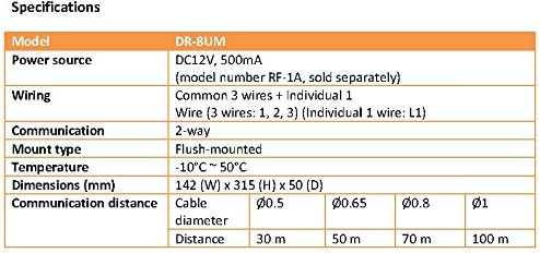
Figure 9.1: Technical specifications table for the Commax DR-8UM, detailing model, power source, wiring, communication type, mount type, temperature range, dimensions, and communication distance based on cable diameter.
| Feature | Detail |
|---|---|
| Model | DR-8UM |
| Power Source | DC12V, 1Amp (Commax RF-1A, sold separately) |
| Wiring | Common 3 wires + Individual 1 wire (Wire 3 wires: 1, 2, 3; Individual 1 wire: L1) |
| Communication Type | 2-way audio |
| Mount Type | Flush-mounted |
| Operating Temperature | -10°C ~ 50°C |
| Dimensions (W x H x D) | 142 mm x 315 mm x 50 mm |
| Compatible Interphone | Commax DP-SS series (sold separately) |
10. Warranty and Support
For warranty information and technical support, please refer to the official Commax website or contact your local distributor. Keep your purchase receipt for warranty claims.
For replacement parts, including individual buttons, please contact Commax customer service directly as parts availability may vary.


