1. Introduction
Thank you for choosing the Stryker SR-94HPC 10 Meter Radio. This compact and powerful radio is designed for reliable communication, featuring AM/FM modulation, a full-color TFT display, and robust construction. This manual provides essential information for the proper setup, operation, and maintenance of your SR-94HPC radio to ensure optimal performance and longevity.
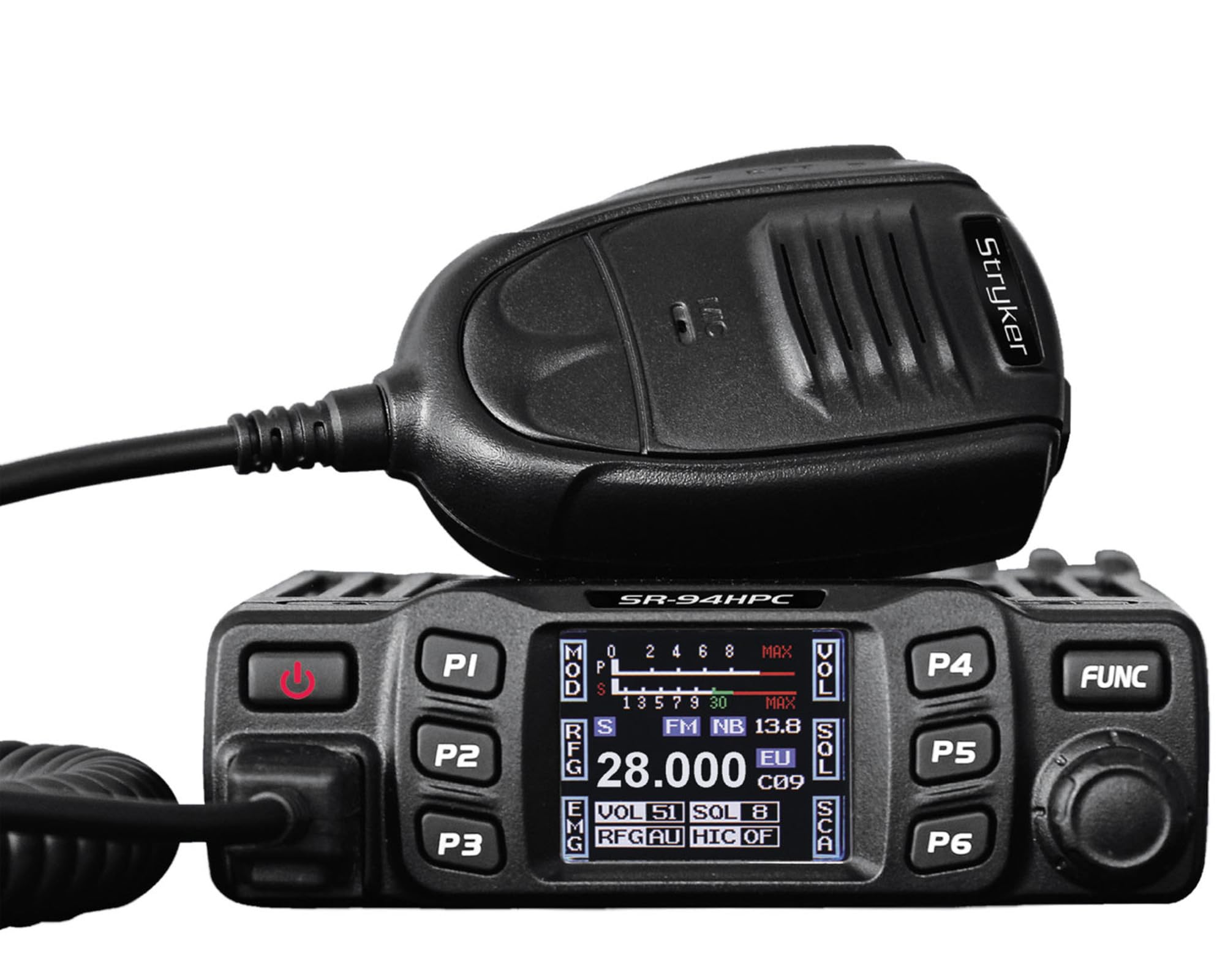
Figure 1: Stryker SR-94HPC 10 Meter Radio. This image shows the compact design of the radio, featuring its front panel with controls and the full-color TFT display.
2. Important Safety Information
Please read and understand all safety instructions before operating the radio. Failure to do so may result in injury, damage to the radio, or voiding the warranty.
- Power Source: Connect the radio only to a 12V or 24V DC power source as specified. Incorrect voltage can damage the unit.
- Antenna: Always connect a properly tuned antenna before transmitting. Transmitting without an antenna or with a poorly tuned antenna can cause damage to the radio's final transistors.
- Heat Dissipation: Ensure adequate ventilation around the radio, especially the heat sink, to prevent overheating during prolonged transmission.
- Water Exposure: While the radio has some water resistance, avoid direct exposure to water or extreme moisture.
- Driving Safety: Do not operate the radio in a manner that distracts you from driving. Prioritize road safety.
- Proposition 65 Warning: This product may expose you to chemicals known to the State of California to cause cancer and birth defects or other reproductive harm. For more information, go to www.P65Warnings.ca.gov.
3. Package Contents
Verify that all items are present in the package:
- Stryker SR-94HPC 10 Meter Radio Unit
- Microphone
- Power Cable
- Mounting Bracket and Hardware
- User Manual (this document)
4. Controls and Functions
The SR-94HPC features a user-friendly interface with a full-color TFT display and intuitive controls. Familiarize yourself with the following:
- Full-Color TFT Display: Shows frequency, voltage, S units, functions, and other operational data. The display is designed for clarity and ease of reading while driving.
- Channel Selector/Encoder: Used to change channels and navigate menu options.
- Volume Control: Adjusts the audio output level.
- Squelch Control: Eliminates background noise when no signal is present.
- Mode Button: Switches between AM and FM modulation modes.
- Function Buttons: Access various radio features and settings. Refer to the on-screen menu for specific functions.
- Microphone Connector: Front-panel connection for the supplied microphone.
- PTT (Push-To-Talk) Button: Located on the microphone, used to transmit.
5. Setup
Follow these steps for initial setup of your SR-94HPC radio:
- Mounting: Securely mount the radio using the provided bracket and hardware in a location that allows for good ventilation and easy access to controls. Ensure the wrap-around cast aluminum heat sink has clear airflow.
- Antenna Connection: Connect a 10-meter antenna with a UHF, SO-239 connector to the antenna port on the rear of the radio. Ensure the antenna is properly tuned for the 28.000 ~ 29.700MHz frequency range to prevent damage to the radio.
- Power Connection: Connect the supplied power cable to the radio's power input. Connect the other end to a stable 12V or 24V DC power source in your vehicle or base station. Observe correct polarity (red to positive, black to negative).
- Microphone Connection: Plug the microphone into the dedicated microphone jack on the front panel of the radio.
- Initial Power On: Once all connections are secure, turn on the radio. The TFT display should illuminate, showing the current operating status.
6. Operating Instructions
This section details the basic operation of your Stryker SR-94HPC radio.
6.1 Power On/Off
Press and hold the power button (usually integrated with the volume knob or a dedicated button) to turn the radio on or off. A quick tap of the power button may mute the audio.
6.2 Channel Selection
Rotate the Channel Selector knob to change the operating frequency or channel. The selected channel will be displayed on the TFT screen.
6.3 Modulation Mode
Press the Mode button to toggle between AM (Amplitude Modulation) and FM (Frequency Modulation) modes. The active mode will be indicated on the display.
6.4 Volume and Squelch Adjustment
- Volume: Adjust the Volume knob to your desired listening level.
- Squelch: Rotate the Squelch knob clockwise until background noise disappears. Rotate counter-clockwise to hear weaker signals. The SR-94HPC may also feature an automatic squelch control (ASC) setting, which can be adjusted via the menu.
6.5 Transmission
To transmit, press and hold the PTT button on the microphone. Speak clearly into the microphone. Release the PTT button to receive. Ensure the antenna is properly connected and tuned before transmitting to avoid damage.
6.6 Display Information
The full-color TFT display provides real-time information, including:
- Frequency/Channel: Current operating frequency or channel number.
- Voltage: Input voltage to the radio.
- S Units: Signal strength indicator for received signals.
- Power Output: Indication of transmitted power.
- SWR: Standing Wave Ratio, indicating antenna tuning efficiency.
7. Maintenance
Proper maintenance ensures the longevity and reliable operation of your SR-94HPC radio.
- Cleaning: Use a soft, dry cloth to clean the radio's exterior and display. Avoid abrasive cleaners or solvents.
- Antenna System: Regularly check your antenna and coaxial cable for damage. Periodically verify your antenna's SWR (Standing Wave Ratio) to ensure efficient power transfer and prevent damage to the radio. An SWR meter can be used for this purpose.
- Heat Sink: Ensure the wrap-around cast aluminum heat sink on the rear of the radio remains free of obstructions to allow for proper heat dissipation, especially during high-power transmissions.
- Connections: Periodically check all cable connections (power, antenna, microphone) to ensure they are secure and free from corrosion.
8. Troubleshooting
If you encounter issues with your SR-94HPC, refer to the following common problems and solutions:
| Problem | Possible Cause | Solution |
|---|---|---|
| Radio does not power on. | No power connection; incorrect voltage; blown fuse. | Check power cable connections; verify 12V/24V DC source; inspect and replace fuse if necessary. |
| No audio from speaker. | Volume too low; squelch set too high; speaker disconnected. | Increase volume; decrease squelch; check speaker connection. |
| "Error" message on display during transmission. | High SWR (Standing Wave Ratio); antenna not connected or poorly tuned. | Check antenna connection; tune antenna using an SWR meter. Do not transmit until SWR is acceptable. |
| Poor transmission or reception range. | Antenna issues; environmental interference; low power setting. | Verify antenna tuning and condition; check for local interference; ensure power output is set correctly. |
If the problem persists after attempting these solutions, please contact Stryker customer support for assistance.
9. Specifications
Detailed technical specifications for the Stryker SR-94HPC 10 Meter Radio:
| Feature | Specification |
|---|---|
| Modulation Mode | AM/FM |
| Frequency Range | 28.000 ~ 29.700MHz (FM), 28.000 ~ 29.700MHz (AM) |
| Frequency Tolerance | ±5.0ppm |
| Input Voltage | 12V/24V DC |
| Frequency Control | PLL Synthesizer |
| Operating Temperature Range | -4°F to +131°F (-20°C to +55°C) |
| Antenna Connector | UHF, SO-239 |
| Power Output | 4 Watts FM/AM / 10 Watts AM/FM (PEP up to 45+ watts) |
| Transmission Interference | Inferior to 4nW (-54dBm) |
| Frequency Response | 300-3000Hz |
| Modulated Signal Distortion | Inferior to 5% |
| Output Impedance | 50 ohms |
| Image Rejection | 70dB |
| Adjacent Channel Rejection | 60dB |
| IF Frequencies | 1st: 10.695MHz, 2nd: 455KHz |
| Dimensions (WxDxH) | 4.88” x 6.42” x 1.54” (12.4cm x 16.3cm x 3.9cm) |
| Weight | Approx. 1.48 lbs (0.67 kg) |
| Special Features | Backlit Keys, Full-color TFT Display |
10. Warranty and Support
Stryker Radios are manufactured to high-quality standards. For warranty information, please refer to the warranty card included with your product or visit the official Stryker Radios website. Keep your purchase receipt as proof of purchase.
For technical support, troubleshooting assistance beyond this manual, or service inquiries, please contact Stryker customer support through their official channels. Contact information can typically be found on the manufacturer's website.


