1. Product Overview
The Dial Manufacturing 7112 Cooler Wall Switch is a rotary control device designed for evaporative coolers. It provides multiple operational settings to manage your cooler's fan and pump functions. This switch is a UL Recognized Component, ensuring compliance with safety standards.
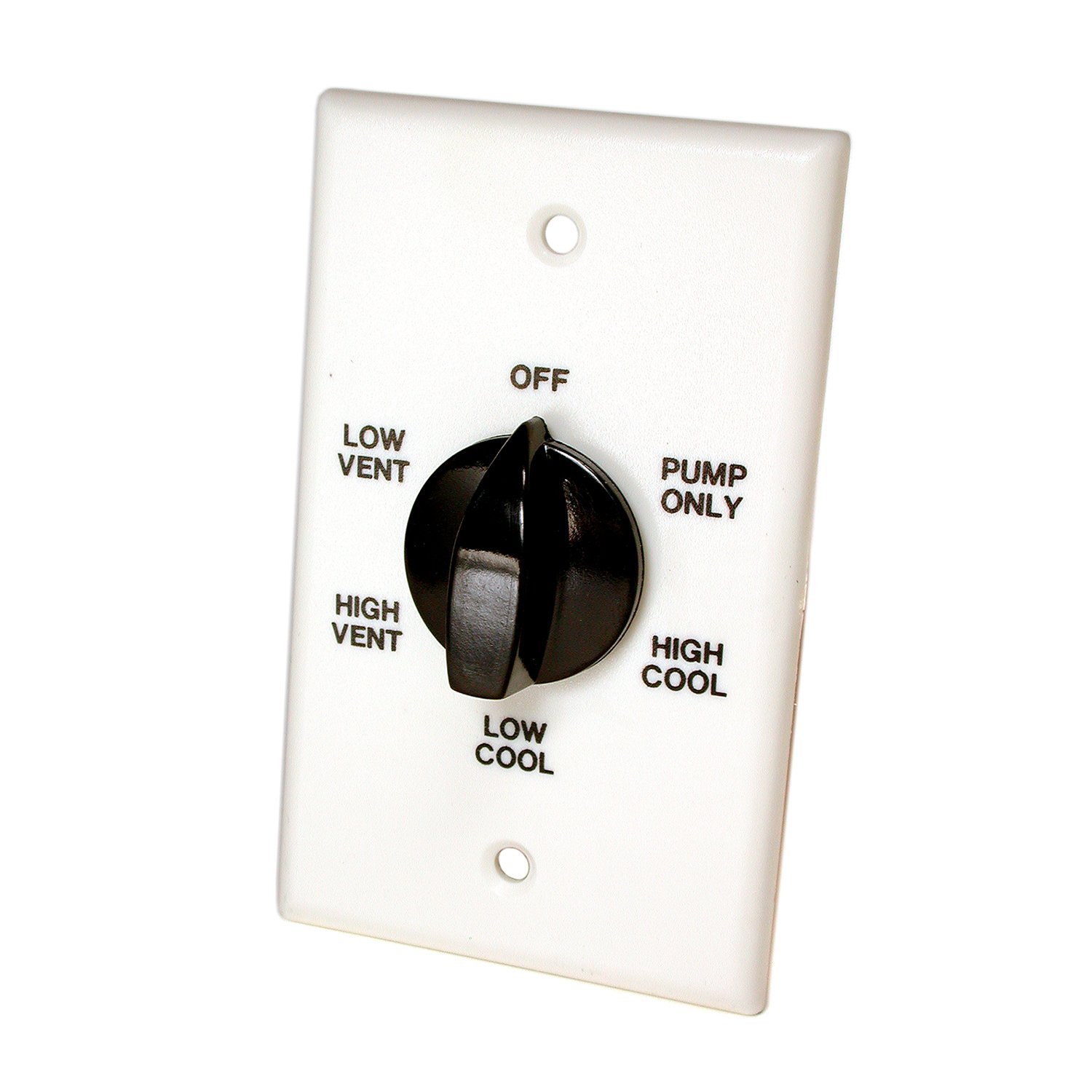
Image: Dial Manufacturing 7112 Cooler Wall Switch, showing its rotary knob and wall plate.
2. Safety Information
- WARNING: Always disconnect power at the circuit breaker or fuse box before installing, servicing, or removing the switch to prevent electrical shock.
- Installation should be performed by a qualified electrician or a knowledgeable individual familiar with electrical wiring.
- Ensure all wiring connections are secure and comply with local electrical codes.
- Do not exceed the specified electrical ratings of the switch (13.8 Amps, 120 Volts).
- This product contains chemicals known to the State of California to cause cancer and birth defects or other reproductive harm (Proposition 65 warning). Wash hands after handling.
3. Package Contents
Verify that all components are present before beginning installation:
- Dial Manufacturing 7112 Cooler Wall Switch
- Mounting Screws
- Wiring Diagram
4. Setup and Installation
Follow these general steps for installing your cooler wall switch. Refer to the included wiring diagram for specific connection details.
- Disconnect Power: Turn off the power to the cooler circuit at the main electrical panel. Confirm power is off using a voltage tester.
- Remove Old Switch (if applicable): Carefully remove the existing wall switch, noting the wiring connections.
- Wire the New Switch: Connect the electrical wires to the terminals on the Dial 7112 switch according to the provided wiring diagram. This switch uses screw-type connectors. Ensure all connections are tight and secure.
- Mount the Switch: Insert the switch into the wall box and secure it with the provided mounting screws.
- Install Wall Plate: Attach the decorative wall plate over the switch.
- Restore Power: Turn the power back on at the main electrical panel.
- Test Operation: Test the switch to ensure proper functionality of your evaporative cooler.
Note: When used with single-speed motors, only 4 of the 6 switch positions will be utilized for operation.
5. Operating Instructions
The Dial Manufacturing 7112 Cooler Wall Switch features a rotary knob for selecting various operational modes. Rotate the knob to the desired setting:
- OFF: Turns off all cooler functions (fan and pump).
- FAN LOW: Activates the fan at a low speed (if applicable).
- FAN HIGH: Activates the fan at a high speed (if applicable).
- PUMP: Activates only the water pump for cooling.
- PUMP + FAN LOW: Activates both the pump and the fan at a low speed.
- PUMP + FAN HIGH: Activates both the pump and the fan at a high speed.
The specific functions available may vary slightly depending on your evaporative cooler model and whether it has a single or multi-speed motor.
6. Maintenance
The Dial 7112 Cooler Wall Switch requires minimal maintenance. To ensure continued reliable operation:
- Periodically inspect the switch and wall plate for any signs of damage or wear.
- Gently wipe the surface with a dry, soft cloth to remove dust or dirt. Do not use abrasive cleaners or liquids directly on the switch.
- If you notice any unusual behavior, such as flickering lights or intermittent operation, disconnect power and inspect the wiring connections for looseness.
7. Troubleshooting
If your cooler is not functioning correctly after switch installation, consider the following:
- No Power to Cooler: Check the circuit breaker or fuse for the cooler circuit. Ensure it is in the 'ON' position. Verify that the main power supply to the switch is active.
- Incorrect Functionality: Review the wiring diagram provided with the switch. Ensure all wires are connected to the correct terminals. Loose connections can cause intermittent operation or failure.
- Only 4 Positions Work: This is normal for single-speed evaporative cooler motors. The switch is designed to accommodate both single and multi-speed systems.
- Switch Feels Loose: Disconnect power and check the mounting screws securing the switch to the wall box. Tighten if necessary.
If issues persist after checking these points, consult a qualified electrician.
8. Specifications
| Specification | Detail |
|---|---|
| Model Number | 7112 |
| Brand | Dial Manufacturing |
| Operation Mode | Manual |
| Current Rating | 13.8 Amps |
| Operating Voltage | 120 Volts |
| Contact Type | Normally Open |
| Connector Type | Screws |
| Mounting Type | Wall Mount |
| Actuator Type | Rotary |
| Number of Positions | 6 |
| Compatible Devices | Evaporative coolers with 1/3 to 1 HP motors |
| Contact Material | Copper, Brass |
| Item Dimensions (L x W x H) | 5 x 5 x 2 inches |
9. Warranty Information
This product comes with a manufacturer's warranty. For specific details regarding warranty coverage, duration, and claims process, please refer to the documentation included with your purchase or contact Dial Manufacturing directly.
10. Support
For technical assistance, replacement parts, or further inquiries about your Dial Manufacturing 7112 Cooler Wall Switch, please contact Dial Manufacturing customer support. Contact information can typically be found on the product packaging or the official Dial Manufacturing website.


