1. Introduction
This manual provides comprehensive instructions for the installation, operation, and maintenance of your Commax 4-Apartment Building Audio Intercom Set, model DR-4UM/DP-SS. This system is designed to facilitate communication between visitors at the building entrance and residents in up to four apartments, including a door release function.

Figure 1: Commax 4-Apartment Audio Intercom Set components.
2. Package Contents
Please verify that all items listed below are included in your package:
- 1x Commax 4-button Lobby Panel (Model: DR-4UM)
- 4x Commax Household Handsets (Model: DP-SS)
- 1x 12V 1.5A Power Supply (Model: RF-12015S)
- 2x 4-pin Connectors
- 1x Instruction Manual (this document)
Note: Accessories such as electric door strike, power supply for electric door strike, and wiring cables are not included and must be purchased separately.
3. Safety Information
Read and understand all safety instructions before installation and operation. Failure to follow these instructions may result in electric shock, fire, or damage to the product.
- Electrical Safety: Ensure power is disconnected before performing any wiring or installation. All wiring should be performed by a qualified electrician in accordance with local electrical codes.
- Voltage: Use only the specified 12V DC power supply. Using an incorrect power supply can damage the unit and void the warranty.
- Environment: The lobby unit is designed for outdoor use, but ensure it is protected from extreme weather conditions if possible. Handsets are for indoor use only.
- Wiring: Do not short-circuit wires. Ensure all connections are secure and properly insulated.
4. Setup and Installation
4.1. Lobby Unit (DR-4UM) Installation
The DR-4UM lobby unit is designed for flush-mounted installation. It should be installed at the building entrance where visitors can easily access it.

Figure 2: DR-4UM Lobby Unit with mounting details.
- Prepare the Opening: Create an opening in the wall according to the dimensions provided in Figure 3. The unit requires a flush-mounted recess.
- Mount the Back Box: Secure the back box (not explicitly shown as separate, but implied by flush mount) into the prepared opening.
- Wiring: Connect the necessary wiring to the lobby unit. This includes power (DC12V, 1.5A), communication wires to the handsets, and optional door strike wiring. Refer to Section 4.3 for wiring details.
- Secure the Unit: Insert the lobby unit into the back box and secure it using screws.

Figure 3: DR-4UM Lobby Unit Flush Mount Dimensions (Dimensions in mm: 250 height, 130 width, 10 depth for front panel; 122 width, 37 depth for back box).
4.2. Handset (DP-SS) Installation
The DP-SS handsets are designed for surface-mounted installation inside each apartment.

Figure 4: Commax DP-SS Handset.
- Choose Location: Select a suitable indoor location within each apartment, typically near the entrance.
- Mounting Bracket: Secure the mounting bracket to the wall using appropriate screws. Refer to Figure 5 for dimensions.
- Wiring: Connect the communication wires from the lobby unit to the handset. Also, connect the two wires for the door lock if an electric door strike is used. Refer to Section 4.3 for wiring details.
- Attach Handset: Mount the DP-SS handset onto the secured bracket.
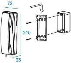
Figure 5: DP-SS Handset Surface Mount Dimensions (Dimensions in mm: 210 height, 72 width, 33 depth).
4.3. Wiring Diagram and Power Supply
The system operates on a 12V DC power supply. The lobby unit (DR-4UM) requires a DC12V, 1.5A power source and provides power to the handsets.
- Lobby Unit Power: Connect the provided 12V 1.5A power supply to the DR-4UM lobby unit.
- Communication Wiring: The system uses a "Common 3 wires + individual 1 wire" configuration for communication between the lobby unit and each handset. Ensure correct polarity and secure connections using the 4-pin connectors.
- Door Lock Wiring: If an electric door strike is used, connect its two wires to the designated terminals on the DP-SS handset. Note that the door strike and its power supply are not included.
- Cable Gauge: Refer to the specifications table (Section 7) for recommended wire gauges based on transmission distance.
5. Operation
5.1. Calling an Apartment
- Visitor Action: At the lobby unit, the visitor presses the button corresponding to the desired apartment.
- Resident Notification: The handset in the selected apartment will ring, indicating a visitor call.
5.2. Answering a Call
- Resident Action: When the handset rings, lift the receiver to establish two-way audio communication with the visitor at the lobby unit.
- Conversation: Speak clearly into the handset.
5.3. Door Release Function
If an electric door strike is connected to the system:
- During a Call: While communicating with a visitor via the handset, press the door release button on the handset.
- Door Unlocks: This action will momentarily activate the electric door strike, unlocking the entrance door.
- End Call: Place the receiver back on the handset to end the call.
6. Maintenance
To ensure the longevity and optimal performance of your Commax intercom system, follow these simple maintenance guidelines:
- Cleaning: Wipe the lobby unit and handsets with a soft, dry cloth. For stubborn dirt, use a slightly damp cloth and mild detergent, then wipe dry immediately. Do not use abrasive cleaners or solvents.
- Inspection: Periodically check all visible wiring for signs of wear or damage. Ensure all connections remain secure.
- Environmental Protection: While the lobby unit is robust, protecting it from direct, heavy rain or snow can extend its lifespan.
7. Troubleshooting
If you encounter issues with your intercom system, refer to the following common problems and solutions:
- No Power to Units:
- Check if the 12V power supply is properly connected to the lobby unit and plugged into a working electrical outlet.
- Verify that the power supply is functioning correctly.
- Inspect power wiring for breaks or loose connections.
- No Audio (Lobby Unit to Handset or vice versa):
- Ensure all communication wires are correctly connected and secure at both the lobby unit and the handset.
- Check for any damage to the wiring.
- Confirm the handset receiver is properly lifted when attempting to communicate.
- Door Release Not Working:
- Verify that an electric door strike is properly installed and connected to the handset.
- Ensure the door strike has its own dedicated power supply, if required (not included with this intercom set).
- Check the wiring between the handset and the door strike for continuity and secure connections.
- Handset Not Ringing:
- Confirm the correct apartment button is being pressed on the lobby unit.
- Check communication wiring between the lobby unit and the specific handset.
If the problem persists after attempting these solutions, please contact your installer or the product supplier for further assistance.
8. Specifications
Detailed technical specifications for the Commax DR-4UM Lobby Unit and DP-SS Room Station are provided below:

Figure 6: Commax DR-4UM and DP-SS Specifications Table.
| Door Station DR-4UM | |
|---|---|
| Model Number | DR-4UM |
| Power Source | DC12V, 500mA |
| Communication Ways | Synchronous Communication |
| Wiring | Common 3 wires + individual 1 wire |
| Compatible Room Unit | Commax Handset: DP-SS, DP-TS, DP-KSS |
| Transmission Distance | Ø0.5mm/AWG24: 30m/90ft Ø0.65mm/AWG22: 50m/150ft Ø0.8mm/AWG20: 70m/210ft Ø1.0mm/AWG18: 100m/300ft |
| Temperature | -10°C to +50°C (tested up to -40°C) |
| Dimensions (mm) | 142x250x50 (mm) |
| Mount Type | Flush-mounted type |
| Room Station DP-SS | |
|---|---|
| Model | DP-SS |
| Power Source | DC12V (from door station) |
| Mount Type | Surface mounted |
| Wiring | to door station: 4 wires to door lock: 2 wires |
| Dimensions with Handset | 70x210x80 (mm) |
| Operating Temperature | 0°C ~ 50°C |
9. Warranty and Support
For warranty information, technical support, or service inquiries, please contact the retailer or authorized distributor from whom you purchased the Commax 4-Apartment Building Audio Intercom Set. Please retain your proof of purchase for warranty claims.


