1. Introduction
This manual provides comprehensive instructions for the installation, setup, operation, and maintenance of the FAS BFT FL130 PhotoCell Gate Sensor. Please read this manual thoroughly before installation and use to ensure proper function and safety.
The BFT FL130 PhotoCells are designed as a pair of photoelectric sensors with a double relay, typically used for gate automation systems. They are normally energized on exit and detect obstructions in the gate's path.
2. Product Overview
The FAS BFT FL130 PhotoCell Gate Sensor system consists of a transmitter and a receiver unit. These units work in conjunction to create an infrared beam, which, when interrupted, signals the gate control system.
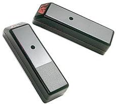
Figure 1: FAS BFT FL130 PhotoCell Gate Sensors. These are the two main components of the system, designed for surface mounting.
Key Features:
- Durable Metal Housing: Constructed with robust metal for enhanced longevity and protection against environmental factors.
- High Sensitivity: Engineered for precise detection of movement or obstructions within its operational range.
- Wide Range of Motion: Capable of detecting movement from various directions, ensuring comprehensive coverage.
- Easy Installation: Features a surface mount design for straightforward installation on flat surfaces.
- Reliable Performance: Provides consistent and dependable operation for secure access control systems.
3. Safety Information
WARNING: Improper installation or use can lead to serious injury or property damage. Always follow local electrical codes and safety regulations.
- Disconnect power to the gate operator before performing any installation or maintenance.
- Ensure all wiring is correctly connected and insulated to prevent electrical hazards.
- Do not modify the photocells or their components.
- Keep children and pets away from the gate area during installation and operation.
- If you are unsure about any part of the installation process, consult a qualified technician.
4. Installation
4.1. Mounting Location
The BFT FL130 PhotoCells are designed for surface mounting. They should be mounted on flat, stable surfaces, parallel to each other, at a height of approximately 40 to 60 cm (15.7 to 23.6 inches) from the ground. Ensure there are no obstructions between the transmitter and receiver units.
- Optimal Range: The effective range is 30 feet (approximately 9 meters) or less. Position the units within this range for reliable operation.
- Alignment: Precise alignment between the transmitter and receiver is crucial for proper function.
- Environmental Factors: Avoid mounting in direct sunlight if possible, or use appropriate shielding to prevent interference.
4.2. Wiring Instructions
The BFT FL130 PhotoCells feature a double relay and are normally energized on exit. Refer to the wiring diagram provided with your gate operator control board for specific connection points. General wiring steps include:
- Identify the power supply terminals (typically 12-24V AC/DC) on both the transmitter and receiver units.
- Connect the power supply to both units, ensuring correct polarity.
- Connect the relay output from the receiver unit to the safety input terminals on your gate operator control board. These are typically labeled "PhotoCell," "Safety Beam," or similar.
- Ensure all connections are secure and protected from moisture.
5. Setup and Alignment
After physical installation and wiring, the photocells need to be aligned and tested.
- Power On: Apply power to the gate operator system.
- Initial Check: Observe the indicator lights on both the transmitter and receiver units. A steady light typically indicates power and proper function.
- Alignment: Carefully adjust the position of the receiver unit (and transmitter if necessary) until the alignment indicator light (if present) on the receiver unit illuminates steadily, indicating a strong beam connection.
- Testing: Once aligned, test the photocells by interrupting the beam with an object (e.g., your hand or a small box). The gate operator should stop or reverse its movement when the beam is broken.
- Fine-tuning: If the gate does not respond correctly, re-check alignment and wiring.
6. Operating Instructions
The BFT FL130 PhotoCells operate automatically as a safety device for your gate system. They do not require manual operation.
- When the gate is closing, if the infrared beam between the photocells is interrupted, the gate's movement will stop or reverse to prevent impact.
- The system will typically resume normal operation once the obstruction is removed and the beam is clear.
- Ensure the area around the photocells is clear of debris or vegetation that could block the beam.
7. Maintenance
Regular maintenance ensures the longevity and reliable operation of your BFT FL130 PhotoCell Gate Sensors.
- Cleaning: Periodically clean the lenses of both the transmitter and receiver units with a soft, damp cloth to remove dirt, dust, or spiderwebs. Do not use abrasive cleaners.
- Inspection: Regularly inspect the wiring for any signs of damage, fraying, or loose connections.
- Alignment Check: Occasionally verify that the photocells remain properly aligned. If the gate exhibits unusual behavior, check alignment first.
- Obstruction Removal: Keep the area around the photocells clear of any plants, debris, or objects that could obstruct the beam.
8. Troubleshooting
| Problem | Possible Cause | Solution |
|---|---|---|
| Gate does not close or reverses immediately. | Beam is obstructed or misaligned. | Check for obstructions. Clean lenses. Re-align photocells. |
| Photocell indicator light is off. | No power or faulty wiring. | Verify power supply. Check all wiring connections. |
| Gate closes even with an obstruction. | Photocells are not connected or faulty. | Check wiring to the gate operator control board. Test photocell function. Replace if faulty. |
| Intermittent operation. | Poor alignment, dirty lenses, or environmental interference. | Clean lenses. Re-align carefully. Check for strong sunlight interference. |
9. Specifications
- Part Number: BFT-FL130-TD
- Model Number: BFT-FL130-TD
- Style: Modern
- Power Source: DC
- Item Package Quantity: 1 (pair of photocells)
- Type of Bulb: LED
- Mounting Type: Surface mount
- Typical Mounting Height: 40-60 cm from ground
- Maximum Range: 30 ft (approx. 9 meters)
- ASIN: B01M8LOJGP
- First Available: February 10, 2014
10. Warranty and Support
For warranty information and technical support, please refer to the documentation provided with your purchase or contact your authorized FAS dealer. Keep your proof of purchase for warranty claims.
For further assistance, please visit the FAS official website or contact their customer service department.


