1. Introduction and Overview
This manual provides essential information for the safe and effective operation of your Dayton Time Delay Relay, Model 31EE11. This versatile relay is designed to offer a wide range of timing functions and universal voltage input, making it suitable for various industrial and scientific applications.
The compact unit integrates 10 distinct timing functions and a programmable time range from 0.1 seconds up to 10 days. Its 16A SPDT (Single Pole Double Throw) output contacts are capable of handling most general-purpose loads. The relay features LED indicators for operational status: a green LED illuminates when input voltage is applied, and a red LED blinks during the timing cycle, becoming steady when the output relay is energized. Its 17.5mm enclosure is designed for easy installation onto a 35mm DIN rail, optimizing space and reducing installation time.
2. Safety Information
Please read and understand all safety instructions before installing or operating this device. Failure to comply with these instructions may result in electrical shock, fire, serious injury, or death.
- Qualified Personnel Only: Installation and maintenance should only be performed by qualified electrical personnel.
- Disconnect Power: Always disconnect all power sources before installing, wiring, or servicing the relay.
- Voltage Compatibility: Ensure the supply voltage matches the relay's specified voltage range (12 to 240VAC/DC).
- Proper Wiring: Use appropriate wire gauges and ensure all connections are secure and comply with local electrical codes. Refer to the wiring diagram on the device and in this manual.
- Environmental Conditions: Do not expose the relay to moisture, excessive heat, or corrosive environments.
3. Features
The Dayton 31EE11 Time Delay Relay boasts a comprehensive set of features designed for flexibility and reliability:
- Multi-Function Timing: Offers 10 distinct timing functions, including:
- Flasher (Off First)
- Flasher (On First)
- Interval On
- Off Delay
- Off/On Delay
- On Delay
- One Shot
- Latching Relay
- Pulse Generator
- Watchdog
- Universal Voltage Input: Operates on a wide range of AC/DC voltages from 12V to 240V.
- Wide Time Range: Programmable time settings from 0.1 seconds to 10 days.
- High Current Output: 15A SPDT contacts suitable for various loads.
- LED Status Indicators: Green LED for power indication, red LED for timing and output status.
- Compact Design: 17.5mm wide enclosure for space-saving installation.
- DIN Rail Mount: Snaps onto standard 35mm DIN rails for quick and secure installation.
- Adjustable Settings: Time and function selection via integrated potentiometers.
4. Installation and Setup
Proper installation is crucial for the reliable operation of the time delay relay. Follow these steps carefully:
- Mounting:
The relay is designed for DIN rail mounting. Snap the relay securely onto a standard 35mm DIN rail in your control panel or enclosure. Ensure it is firmly seated to prevent vibration.
- Wiring Connections:
Before making any connections, ensure all power to the circuit is disconnected. The relay uses screw clamp terminals for electrical connections. Refer to the diagram below for terminal identification and wiring.
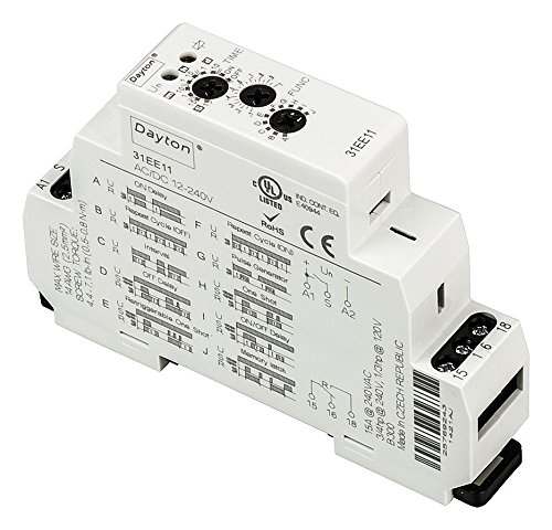
Figure 4.1: Dayton 31EE11 Time Delay Relay Overview. This image displays the Dayton 31EE11 Time Delay Relay, highlighting its compact design and key features. Visible elements include the "Dayton" brand name, model number "31EE11", input voltage range "AC/DC 12-240V", and various certifications (UL Listed, RoHS, CE). The top of the unit features two rotary potentiometers for "TIME" adjustment and "FUNC" (function) selection. The side of the relay provides a detailed diagram illustrating the 10 timing functions (A-J) and their corresponding settings. Wiring terminals are clearly marked: A1 and A2 for coil voltage input, and 15, 16, 18 for the SPDT output contacts. Important specifications such as maximum wire size (14 AWG / 2.5mm²) and screw torque (4.4-7.1 lb-in / 0.5-0.8 N-m) are also printed on the side, along with contact ratings (15A @ 240VAC, 3/4hp @ 240V, 1/3hp @ 120V) and country of manufacture (Made in Czech Republic).
- Coil Power (A1, A2): Connect your 12-240VAC/DC power supply to terminals A1 and A2.
- Output Contacts (15, 16, 18):
- Terminal 15: Common (COM)
- Terminal 16: Normally Closed (NC)
- Terminal 18: Normally Open (NO)
- Wire Specifications: Ensure wire size does not exceed 14 AWG (2.5mm²).
- Screw Torque: Tighten terminal screws to 4.4-7.1 lb-in (0.5-0.8 N-m) to ensure secure connections and prevent loosening.
- Function Selection:
Use the "FUNC" rotary dial on the top of the relay to select one of the 10 available timing functions (A through J). Refer to the function diagram printed on the side of the relay for detailed descriptions of each function's behavior.
- Time Setting:
Use the "TIME" rotary dial to set the desired time delay. The dial allows for precise adjustment within the selected time range. The time range itself is typically set by a smaller internal switch or is automatically scaled based on the function selected (refer to the device markings for specific scaling if applicable).
5. Operation
Once installed and configured, the Dayton 31EE11 Time Delay Relay operates automatically based on the selected function and time setting.
- Power On: Apply power to terminals A1 and A2. The green LED will illuminate, indicating that the relay is receiving input voltage.
- Timing Cycle: Depending on the selected function, the red LED will begin to blink during the active timing cycle.
- Output Energized: Once the timing cycle is complete and the output relay is energized, the red LED will become steady. The SPDT contacts (15, 16, 18) will switch their state according to the selected function.
- Function Behavior: Refer to the function diagram on the relay's side for the specific behavior of each timing mode (e.g., On Delay, Off Delay, Flasher).
6. Maintenance
The Dayton 31EE11 Time Delay Relay is designed for long-term, maintenance-free operation under normal conditions.
- Cleaning: If necessary, gently wipe the exterior of the relay with a dry, soft cloth. Do not use abrasive cleaners or solvents.
- No User-Serviceable Parts: The relay contains no user-serviceable parts. Do not attempt to open or repair the unit. Doing so will void the warranty and may cause damage or injury.
- Periodic Inspection: Periodically inspect wiring connections for tightness and signs of wear or corrosion, especially in high-vibration environments.
7. Troubleshooting
If you encounter issues with your time delay relay, refer to the following troubleshooting guide:
| Problem | Possible Cause | Solution |
|---|---|---|
| No LEDs illuminated when power is applied. | No input voltage; incorrect wiring to A1/A2; faulty power supply. | Verify power supply is active. Check wiring to A1 and A2 terminals for correct polarity (if DC) and secure connections. Ensure voltage is within 12-240VAC/DC range. |
| Green LED on, but red LED does not blink or become steady. | Incorrect function selected; time setting too long/short; internal fault. | Verify the "FUNC" dial is set to the desired timing function. Adjust the "TIME" dial to a suitable range. If problem persists, the unit may be faulty. |
| Output contacts do not switch. | Load wiring incorrect; load current exceeds rating; timing cycle not completed. | Check wiring to terminals 15, 16, 18. Ensure load current does not exceed 15A. Confirm the red LED is steady, indicating the timing cycle is complete and the output is energized. |
| Inconsistent timing. | Unstable input voltage; environmental factors (temperature); faulty unit. | Ensure stable power supply. Operate within specified environmental conditions. If issues persist, consider replacing the unit. |
If troubleshooting steps do not resolve the issue, contact Dayton customer support or a qualified electrician.
8. Specifications
| Parameter | Value |
|---|---|
| Model Number | 31EE11 |
| Coil Voltage | 12 to 240VAC/DC |
| AC Contact Rating | 15A @ 240V |
| Contact Form | SPDT (Single Pole Double Throw) |
| Number of Pins | 6 |
| Mounting Type | 35mm DIN Rail |
| Power Consumption | 3.0VA |
| Adjustment Method | Potentiometer |
| Minimum Time Setting | 0.10 seconds |
| Maximum Time Setting | 10 days |
| Status Indicator | LED (Green for Power, Red for Timing/Output) |
| Contact Material | Silver Alloy |
| Electrical Connection | Screw Clamp |
| Frequency | 50 Hz, 60 Hz |
| Product Dimensions (H x W x D) | 3.55" x 2.52" x 0.69" (Body); 3 x 0.75 x 3.75 inches (Overall) |
| Weight | 1.5 Pounds |
| Manufacturer | CAI - DAYTON |
| Standards | UL, CE |
9. Warranty and Support
Specific warranty details for the Dayton 31EE11 Time Delay Relay are not provided in this document. For information regarding warranty coverage, technical support, or service, please contact Dayton customer service directly or refer to the official Dayton website.
It is recommended to keep your purchase receipt as proof of purchase for any warranty claims.