
Matsutec HA-102
Matsutec HA-102 Marine AIS Transponder User Manual
Model: HA-102
1. Introduction
The Matsutec HA-102 is a Class B Automatic Identification System (AIS) transponder designed for marine use. It functions as both a receiver and transmitter, enhancing navigational safety by allowing vessels to transmit their position, speed, course, and other data, while also receiving similar information from other AIS-equipped vessels and shore stations. This manual provides detailed instructions for the installation, operation, and maintenance of your HA-102 unit.

Figure 1.1: Matsutec HA-102 AIS Transponder and Accessories
This image displays the Matsutec HA-102 AIS Transponder unit along with its essential accessories. The main transponder unit is black with "AIS TRANSPONDER" printed on it, featuring a red safety alarm button. Accompanying it are a data/power cable, a software CD, and small installation components, providing a complete overview of the product package.
2. Key Features
- Dual Channel Function: Two TDMA receivers simultaneously receive data on two independent channels, while one TDMA transmitter alternates transmission on two independent channels.
- CSTDMA Function: Utilizes Carrier-Sense Time Division Multiple Access to prevent and resolve communication conflicts, ensuring reliable data exchange.
- External Serial Data Interface: Equipped with RS-422 and RS-232 ports for versatile connectivity with other marine electronics.
- Safety Message Capability: Transmits and receives safety messages, including an integrated "SOS" safety button for emergency situations.
- Multiple Operation Modes: Supports Carrier-sense mode, assigned mode, and polled mode for flexible operation.
- Internal GPS Receiver: Provides accurate position, Course Over Ground (COG), and Speed Over Ground (SOG) data.
- Compatibility: Can be connected to various devices compatible with GPS and PC, PDA, ECDIS, RADAR, etc.
- DSC Reception Support: Supports Digital Selective Calling (DSC) reception based on the TDMA channel.
- Status Indicators: Features LED indicators for power, error, time-out, and operational status.
3. Setup and Installation
Proper installation is crucial for the optimal performance of your HA-102 transponder. Ensure all connections are secure and follow the guidelines below.
3.1 Physical Installation
The HA-102 unit is designed for panel mounting. Consider a location that is protected from direct exposure to harsh weather conditions and allows for proper cable routing.

Figure 3.1: HA-102 Dimensions
This image illustrates the physical dimensions of the HA-102 unit, showing a width of 234mm, a height of 40mm, and a depth of 167mm. These measurements are essential for planning the mounting location.

Figure 3.2: HA-102 Rear Panel Connections
This image provides a detailed view of the rear panel of the HA-102, highlighting the various connection ports: Power & Data (DC12V-24V), RS232 (DB9), GPS Antenna (TNC connector), and VHF Antenna (Type M connector). Proper identification of these ports is critical for correct wiring.
3.2 Power and Data Connections
The HA-102 operates on a 12V DC power supply (10V-20V). Connect the power and data cable to the designated port on the unit. The unit features external serial data interfaces (RS-422, RS-232) for integration with other marine navigation systems.

Figure 3.3: Power and Data Pinout
This diagram illustrates the pin assignments for the power and data cable. Pin 1 (Red) is Power +, Pin 2 (Black) is Power -, Pin 3 (Green) is TXD, Pin 4 (Yellow) is NC (No Connection), and Pin 5 (Blue) is GND. This information is vital for correct electrical wiring.
The DB9 port is used for static information configuration and NMEA data output (RS232). The aviation header is used for power input and NMEA data output (RS422).
3.3 Antenna Connections
- GPS Antenna: Connect the GPS antenna (optional, Female TNC Connector) to the dedicated GPS port. The internal GPS receiver requires an external antenna for optimal signal reception.
- VHF Antenna: Connect the VHF antenna (optional, Female Type M Connector) to the dedicated VHF port. This antenna is essential for AIS signal transmission and reception.
4. Operating Instructions
Once installed and powered on, the HA-102 will begin operating. Familiarize yourself with its indicators and functions.
4.1 Powering On/Off
Locate the ON/OFF switcher on the unit's front panel. Toggle it to the 'ON' position to power up the device. The 'Power' LED indicator will illuminate.

Figure 4.1: HA-102 Front Panel
This image shows the front panel of the HA-102, featuring the ON/OFF switch, a prominent red safety alarm button, and four LED indicators: Power, RX CHA (Receive Channel A), RX CHB (Receive Channel B), and TX (Transmit). These indicators provide real-time operational status.
4.2 LED Indicators
- Power: Indicates the unit is receiving power.
- RX CHA: Illuminates when receiving data on Channel A.
- RX CHB: Illuminates when receiving data on Channel B.
- TX: Illuminates when transmitting data.
- Error/Alarm: An additional LED (often red) indicates system errors or alarms, such as GPS signal loss or internal malfunction.
4.3 Dual Channel and CSTDMA Functionality
The HA-102's dual-channel capability allows it to monitor two AIS frequencies simultaneously, improving situational awareness. The CSTDMA function automatically manages transmission slots to avoid interference with other AIS units, ensuring efficient and reliable communication.
4.4 Safety Message and SOS Button
The unit is equipped with a dedicated "SOS" safety button. In an emergency, pressing this button will transmit a safety message, alerting other vessels and shore stations to your distress. Ensure your MMSI (Maritime Mobile Service Identity) is correctly programmed for this feature to function.
4.5 Operation Modes
- Carrier-sense mode: Standard operation where the unit listens for available transmission slots.
- Assigned mode: For specific applications where transmission slots are pre-assigned.
- Polled mode: The unit transmits only when requested by a base station.
Configuration of these modes and other static information typically requires connection to a PC with the provided software. Refer to the software manual for detailed instructions on programming your unit.
5. Specifications
Detailed technical specifications for the Matsutec HA-102 AIS Transponder.
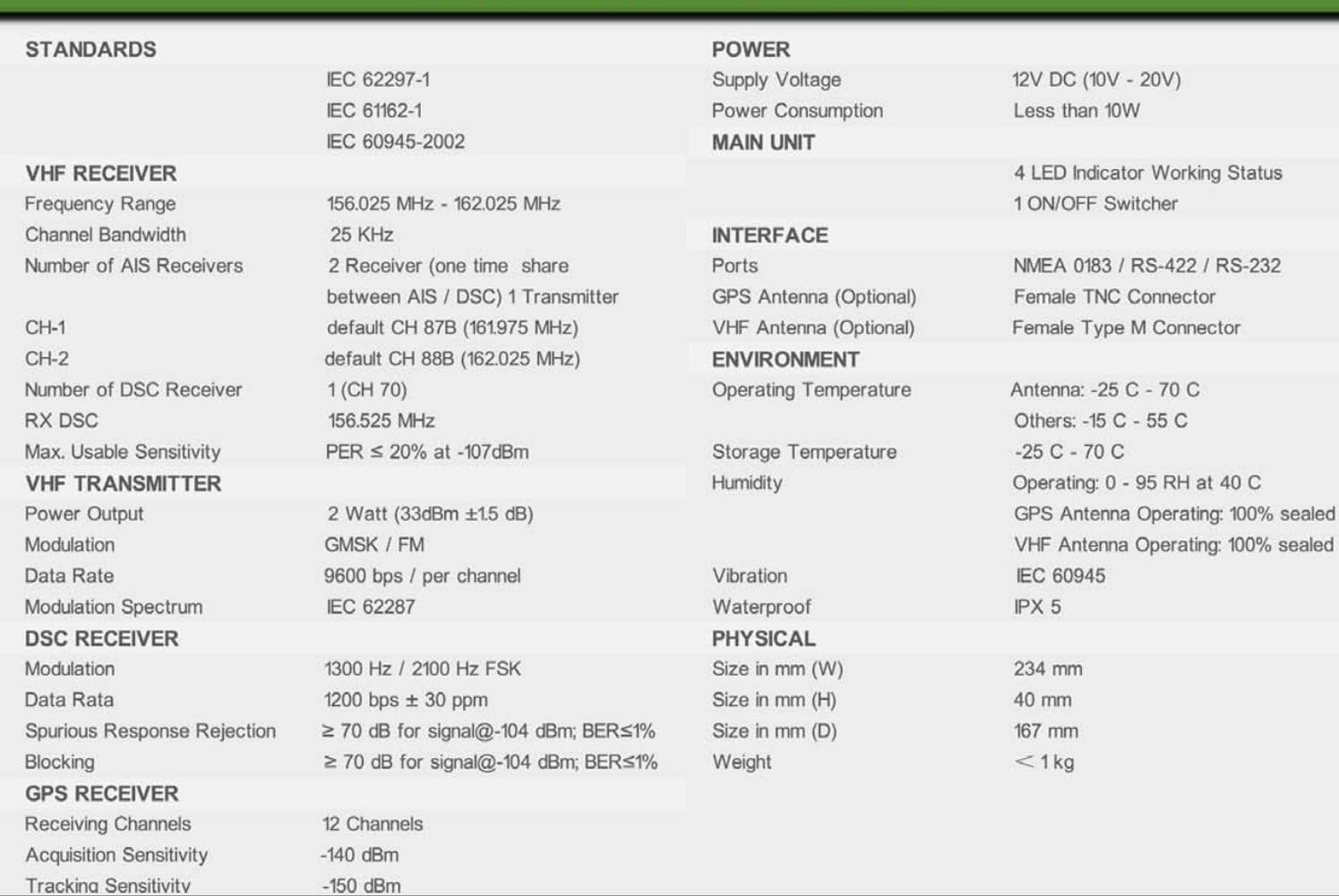
Figure 5.1: Detailed Specifications
This image presents a comprehensive table of technical specifications for the HA-102, covering various aspects such as compliance standards (IEC 62297-1, IEC 61162-1, IEC 60945-2002), VHF receiver and transmitter parameters, DSC receiver details, GPS receiver performance, power requirements, main unit features, interface types, environmental operating conditions, and physical dimensions and weight. This table is crucial for understanding the device's capabilities and limitations.
| Category | Specification |
|---|---|
| Electrical Function | IEC 62297-1 compliant |
| Dual Channel Function | Two TDMA receivers, one TDMA transmitter (alternating) |
| CSTDMA Function | Avoids and solves communication conflicts |
| External Serial Data Interface | RS-422, RS-232 |
| Safety Message | Transmit and receive, equipped with "SOS" button |
| Operation Modes | Carrier-sense, assigned, polled |
| Internal GPS Receiver | Data source for position, COG, SOG |
| Compatibility | GPS, PC, PDA, ECDIS, RADAR, etc. |
| DSC Reception | Based on TDMA channel |
| Alarm & Indication | LED for power, error, time-out, status |
| GPS Receiving Channels | 12 Channels |
| GPS Acquisition Sensitivity | -140 dBm |
| GPS Tracking Sensitivity | -150 dBm |
| GPS Position Accuracy | <2.5m CEP (GPS) without SA |
| GPS Output Rate | 1 Hz |
| Supply Voltage | 12V DC (10V-20V) |
| Power Consumption | Less than 10W |
| LED Indicators | 4 (Working Status) |
| Switcher | 1 ON/OFF Switcher |
| Ports | NMEA 0183/RS-422/RS-232 |
| GPS Antenna (Optional) | Female TNC Connector |
| VHF Antenna (Optional) | Female Type M Connector |
| Dimensions (W x H x D) | 234 mm x 40 mm x 167 mm |
| Weight | <1kg |
6. Maintenance
The Matsutec HA-102 is designed for reliable operation with minimal maintenance. However, regular checks can ensure its longevity and performance.
- Cleaning: Periodically wipe the unit with a soft, damp cloth. Do not use abrasive cleaners or solvents. Ensure the unit is powered off before cleaning.
- Connections: Regularly inspect all cable connections (power, data, antennas) for corrosion, wear, or looseness. Secure any loose connections.
- Antennas: Ensure GPS and VHF antennas are clear of obstructions and securely mounted. Check antenna cables for damage.
- Software Updates: Check the Matsutec website periodically for firmware or software updates for the HA-102. Updates can improve performance and add new features.
- Environmental Protection: While the unit has some water resistance (IPX5), protect it from excessive moisture, extreme temperatures, and direct sunlight when possible.
7. Troubleshooting
If you encounter issues with your HA-102, refer to the following common troubleshooting steps before contacting support.
| Problem | Possible Cause | Solution |
|---|---|---|
| Unit does not power on. | No power supply; incorrect wiring; blown fuse. | Verify power source (10V-20V DC). Check power cable connections (Red for +, Black for -). Inspect inline fuse if present. |
| No GPS signal / GPS error. | GPS antenna not connected; antenna obstructed; faulty antenna. | Ensure GPS antenna is securely connected to the TNC port. Relocate antenna to an unobstructed view of the sky. Test with a known good GPS antenna if available. |
| No AIS targets displayed on plotter. | VHF antenna issue; incorrect data connection; software configuration. | Check VHF antenna connection (Type M port) and cable integrity. Verify NMEA 0183/RS-422/RS-232 data connections to your plotter/PC. Ensure correct baud rates and data protocols are configured in the connected device and the HA-102 software. |
| Unit shows "Error" or "Alarm" LED. | Internal fault; GPS signal loss; MMSI not programmed. | Check GPS signal. If the error persists, it may indicate an internal fault. Ensure your MMSI is correctly programmed using the configuration software. |
| Cannot connect to PC for configuration. | Incorrect serial port settings; driver issues; incompatible OS. | Verify COM port settings and baud rate (typically 38400 for AIS). Install correct USB-to-serial drivers. Note that some older configuration software may require specific operating systems (e.g., Windows 7). |
8. Warranty and Support
Matsutec products are manufactured to high quality standards. For specific warranty terms and conditions, please refer to the documentation provided at the time of purchase or contact your local Matsutec dealer or distributor. For technical support, software downloads, or further assistance, please visit the official Matsutec website or contact their customer service department.
Manufacturer: ShenZhen JINLAILAI Technology Limited.
Related documentsHA-102


Ask a question about this manual
Ask about setup, troubleshooting, compatibility, parts, safety, or missing instructions. Manuals+ will review the question and use this page’s manual context to help answer it.