1. Introduction
This manual provides essential information for the safe and efficient operation of your COTEK SP-4000-124 Pure Sine Wave Inverter. This high-frequency inverter is designed to convert 24VDC battery power into 120VAC household electricity, offering a pure sine wave output suitable for sensitive electronics. Please read this manual thoroughly before installation and use.
2. Safety Instructions
Adherence to these safety guidelines is crucial to prevent personal injury and damage to the inverter or connected equipment.
- Installation must be performed by qualified personnel in accordance with all applicable electrical codes.
- Do not expose the inverter to rain, moisture, or extreme temperatures.
- Ensure proper ventilation around the inverter to prevent overheating.
- Connect the inverter only to a 24VDC power source. Connecting to a different voltage may cause damage.
- Always disconnect the DC power source before performing any maintenance or wiring.
- Ensure the inverter is properly grounded.
- Do not open the inverter casing. There are no user-serviceable parts inside.
3. Product Features
The COTEK SP-4000-124 Inverter incorporates advanced features for reliable power conversion:
- Pure sine wave output for compatibility with all AC loads.
- Power ON/OFF remote control capability via green terminal.
- Input and output are fully isolated for enhanced safety.
- Temperature and load-controlled cooling fan for optimal thermal management.
- User-friendly interface with 3-color LED status indicators.
- Output frequency (50/60 Hz) selectable via DIP switch.
- Output voltage selectable via DIP switch.
- Power saving mode adjustable by variable resistor.
- Comprehensive input protection: Reverse Polarity (Fuse), Under Voltage, Over Voltage.
- Robust output protection: Short Circuit, Overload, Over Temperature.
- Type 1 Indoor Aluminum Enclosure.
- E13 / UL / CE / FCC approved.
4. Product Overview
Familiarize yourself with the physical components and connections of your inverter.

This image displays the COTEK SP-4000-124 Pure Sine Wave Inverter, showcasing its robust blue casing and overall design from an elevated, angled perspective.
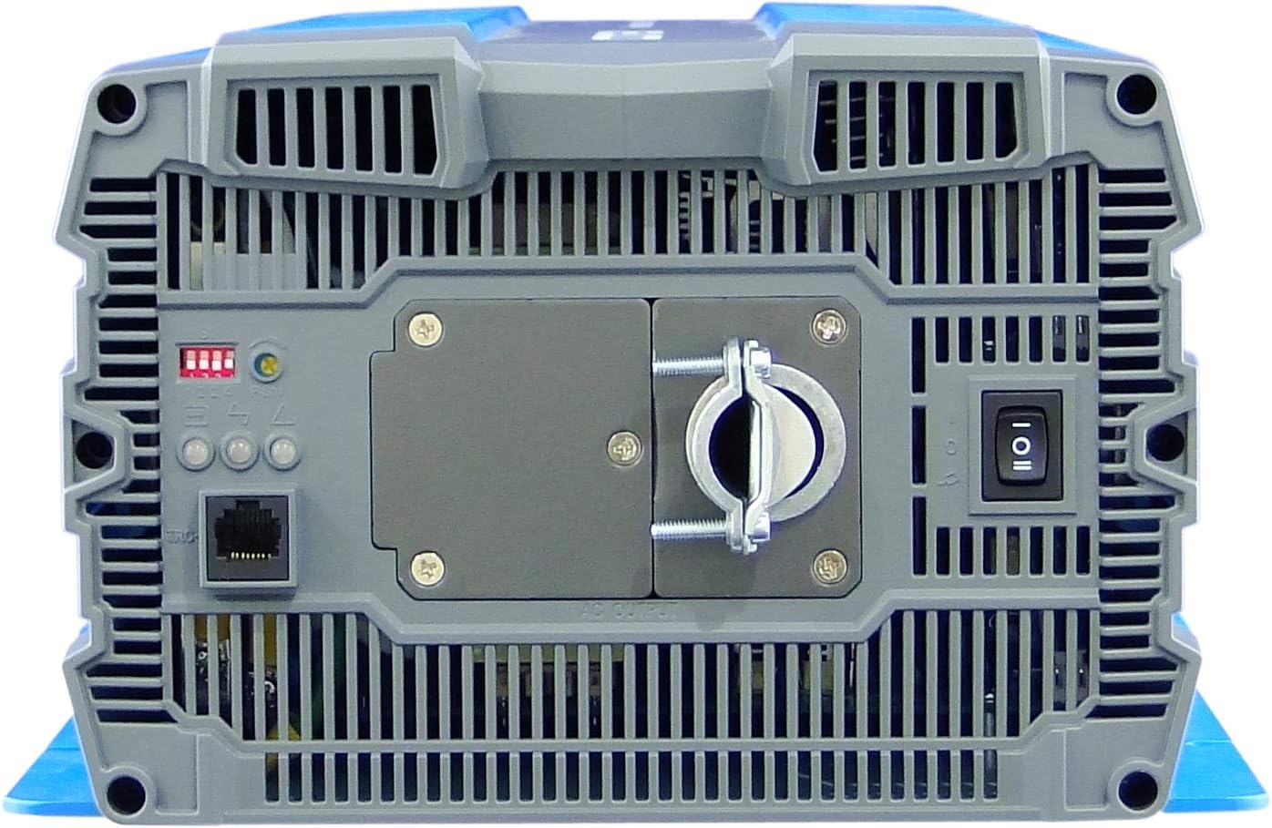
This image shows the rear panel of the COTEK SP-4000-124 Inverter, featuring the hardwire AC output terminal, the main power switch, and a set of LED status indicators and DIP switches for configuration.
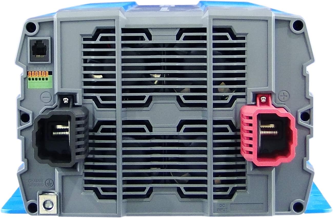
The front panel of the COTEK SP-4000-124 Inverter is depicted, highlighting the robust DC input terminals (red for positive, black for negative) and the chassis ground connection point.

This technical drawing provides detailed mechanical dimensions and outlines of the COTEK SP-4000 series inverter from multiple perspectives (top, front, side), indicating measurements in both millimeters and inches.
5. Setup and Installation
Proper installation is critical for the performance and safety of the inverter. It is highly recommended that installation be performed by a certified electrician or qualified technician.
5.1 Mounting
- Choose a dry, well-ventilated, and cool location.
- Mount the inverter securely to a stable surface, ensuring adequate clearance for airflow around the cooling fins.
- Avoid mounting near flammable materials or in direct sunlight.
5.2 DC Input Connection
- Ensure the DC power source (battery bank) is rated for 24VDC.
- Use appropriately sized cables to minimize voltage drop and ensure safe current handling.
- Connect the positive (+) terminal of the inverter to the positive terminal of the battery bank.
- Connect the negative (-) terminal of the inverter to the negative terminal of the battery bank.
- Install an external DC fuse or circuit breaker between the battery and the inverter for protection.
5.3 AC Output Connection
- The inverter features a hardwire AC outlet. Connect your AC loads directly to this terminal.
- Ensure all AC wiring complies with local electrical codes.
- Do not exceed the inverter's rated output power.
5.4 Grounding
- Connect the inverter's chassis ground terminal to a reliable earth ground point.
6. Operating Instructions
6.1 Powering On/Off
- After all connections are secure, switch on the external DC circuit breaker (if installed).
- Locate the main power switch on the inverter's rear panel and switch it to the 'ON' position.
- The LED indicators will illuminate, indicating the inverter's status.
- To power off, switch the main power switch to 'OFF', then disconnect the DC power source.
6.2 LED Indicators
The 3-color LED indicators provide visual feedback on the inverter's operational status and any potential faults.
- Green: Normal operation.
- Yellow: Warning (e.g., low battery, overload warning). Refer to troubleshooting.
- Red: Fault (e.g., overload shutdown, over-temperature shutdown). The inverter will shut down.
6.3 Output Frequency and Voltage Selection
The inverter allows for selection of output frequency (50/60 Hz) and voltage via DIP switches. Consult the label near the DIP switches for specific settings. Ensure the inverter is off before adjusting DIP switches.
7. Maintenance
Regular maintenance ensures optimal performance and longevity of your inverter.
- Cleaning: Periodically clean the exterior of the inverter and ensure cooling vents are free from dust and debris. Use a dry, soft cloth. Do not use liquid cleaners.
- Connections: Annually inspect all DC and AC connections for tightness and corrosion. Loose connections can cause overheating and poor performance.
- Environment: Ensure the operating environment remains within the specified temperature and humidity ranges.
8. Troubleshooting
This section provides guidance for common issues. For complex problems, contact qualified service personnel.
| Problem | Possible Cause | Solution |
|---|---|---|
| No AC output, Red LED on | Overload, Over-temperature, Input over/under voltage | Reduce load, allow cooling, check battery voltage. Cycle power. |
| Yellow LED on | Low battery voltage warning, minor overload warning | Charge batteries, reduce load. |
| Inverter does not turn on | No DC input power, loose connections, blown DC fuse | Check battery connections, verify battery voltage, inspect DC fuse/breaker. |
| AC output unstable | Poor DC input connections, excessive load, faulty AC wiring | Tighten DC connections, reduce load, inspect AC wiring. |
9. Specifications
Detailed technical specifications for the COTEK SP-4000-124 Pure Sine Wave Inverter.
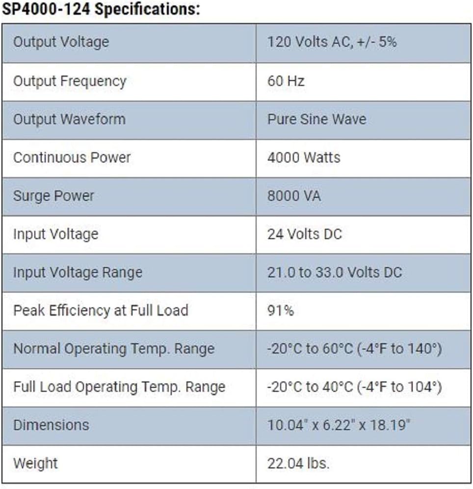
A table detailing the technical specifications of the COTEK SP4000-124 inverter, including output voltage, frequency, waveform, continuous power, surge power, input voltage, efficiency, operating temperature range, dimensions, and weight.
| Parameter | Value |
|---|---|
| Output Voltage | 120 Volts AC, +/- 5% |
| Output Frequency | 60 Hz |
| Output Waveform | Pure Sine Wave |
| Continuous Power | 4000 Watts |
| Surge Power | 8000 VA |
| Input Voltage | 24 Volts DC |
| Input Voltage Range | 21.0 to 33.0 Volts DC |
| Peak Efficiency at Full Load | 91% |
| Normal Operating Temp. Range | -20°C to 60°C (-4°F to 140°) |
| Full Load Operating Temp. Range | -20°C to 40°C (-4°F to 104°) |
| Dimensions (L x W x H) | 18.66 x 12.56 x 9.53 inches (474 x 319 x 242 mm) |
| Weight | 24.8 pounds (11.25 kg) |
10. Warranty and Support
For warranty information and technical support, please refer to the documentation provided with your purchase or contact COTEK customer service directly. Keep your purchase receipt as proof of purchase for warranty claims.


