1. Introduction
This manual provides essential information for the safe and efficient installation, operation, and maintenance of your uxcell 24V DC 7RPM Gear Motor. Please read this manual thoroughly before using the product and retain it for future reference.
2. Safety Information
Observe the following safety precautions to prevent injury and damage to the motor:
- Ensure the power supply voltage matches the motor's rated voltage (24V DC).
- Disconnect power before making any connections or performing maintenance.
- Avoid touching moving parts during operation.
- Do not overload the motor beyond its specified torque limits.
- Install the motor in a well-ventilated area, away from flammable materials.
- If the motor exhibits unusual noise, excessive heat, or smoke, immediately disconnect power.
3. Product Overview
The uxcell 24V DC 7RPM Gear Motor is a micro speed reduction geared motor designed for applications requiring high torque at low rotational speeds. It features an eccentric output shaft for various mechanical linkages.

Figure 3.1: Front view of the uxcell 24V DC 7RPM Gear Motor, showing the output shaft and mounting screws.

Figure 3.2: Rear view of the motor, illustrating the electrical terminals for power connection.
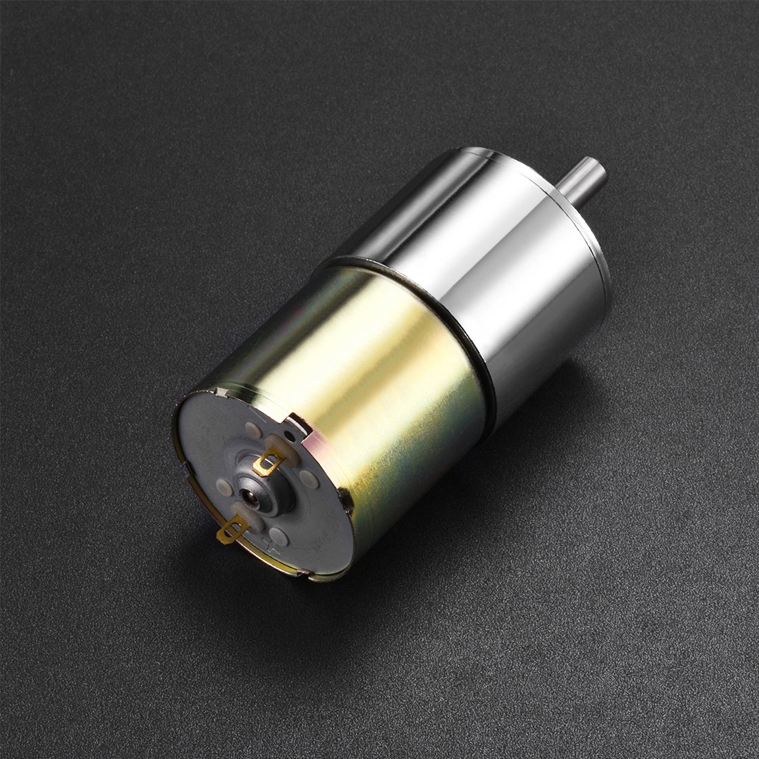
Figure 3.3: Side view of the motor, providing another perspective of its cylindrical body and shaft.

Figure 3.4: Dimensional drawing of the motor, providing key measurements for integration and mounting.
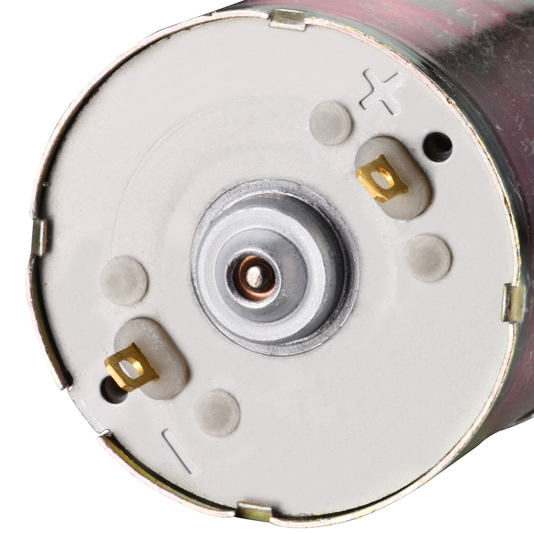
Figure 3.5: Close-up view of the motor's electrical terminals, showing positive and negative markings for correct wiring.
4. Specifications
| Feature | Detail |
|---|---|
| Brand | uxcell |
| Model Number | US-SA-AJD-215306 |
| Voltage | 24V DC |
| Rated Speed | 7 RPM |
| Type | Gear Motor, Micro Speed Reduction |
| Output Shaft | Eccentric |
| Package Dimensions | 5.51 x 3.15 x 1.57 inches |
| Item Weight | 7.05 ounces |
| UPC | 602451864851 |
5. Setup and Installation
5.1 Mounting
The motor can be mounted using the screw holes on the front plate. Ensure the mounting surface is stable and capable of supporting the motor's weight and operational forces. Refer to Figure 3.4 for dimensional details to ensure proper fitment.
- Secure the motor firmly to prevent vibration and movement during operation.
- Allow adequate clearance around the motor for ventilation and to prevent obstruction of the output shaft.
5.2 Wiring
Connect the motor to a 24V DC power supply. The motor terminals are typically marked for polarity (positive '+' and negative '-').
- Connect the positive (+) terminal of the power supply to the positive terminal of the motor.
- Connect the negative (-) terminal of the power supply to the negative terminal of the motor.
- Ensure all connections are secure and insulated to prevent short circuits.
- Reversing the polarity will reverse the direction of rotation of the output shaft.
Note: Always verify the correct voltage and polarity before applying power.
6. Operating Instructions
Once properly installed and wired, the motor is ready for operation.
- Power On: Apply 24V DC power to the motor terminals. The motor shaft will begin to rotate at approximately 7 RPM.
- Direction Control: To change the direction of rotation, reverse the polarity of the DC power supply connected to the motor terminals.
- Load Application: Apply the intended load to the output shaft. Ensure the load does not exceed the motor's torque capabilities to prevent damage.
- Power Off: Disconnect the 24V DC power supply to stop the motor.
Caution: Do not continuously operate the motor under excessive load, as this can lead to overheating and premature failure.
7. Maintenance
The uxcell gear motor is designed for low maintenance. However, periodic checks can extend its lifespan.
- Cleaning: Keep the motor free from dust and debris. Use a soft, dry cloth to wipe the exterior. Do not use solvents or immerse the motor in liquids.
- Connections: Periodically check electrical connections for tightness and signs of corrosion.
- Lubrication: The gear mechanism is factory-lubricated and sealed. No additional lubrication is typically required. Do not attempt to open the gear housing.
- Storage: Store the motor in a dry, cool environment, away from direct sunlight and corrosive substances.
8. Troubleshooting
If you encounter issues with your motor, refer to the following common problems and solutions:
| Problem | Possible Cause | Solution |
|---|---|---|
| Motor does not run | No power, incorrect wiring, faulty power supply, motor overload. | Check power supply connection and voltage. Verify wiring polarity. Reduce load if applicable. Test power supply. |
| Motor runs slowly or with reduced torque | Insufficient voltage, excessive load, internal friction. | Ensure 24V DC supply. Reduce load. Check for obstructions. |
| Motor makes unusual noise | Mechanical obstruction, worn gears (unlikely for new motor), loose mounting. | Check for obstructions. Ensure motor is securely mounted. |
| Motor overheats | Excessive load, continuous operation, poor ventilation. | Reduce load. Allow cooling periods. Ensure adequate ventilation. |
If the problem persists after attempting these solutions, contact the seller or manufacturer for further assistance.
9. Warranty and Support
For warranty information and technical support, please refer to the purchase documentation or contact your retailer. You may also visit the official uxcell store for product information and support resources:


