1. Introduction
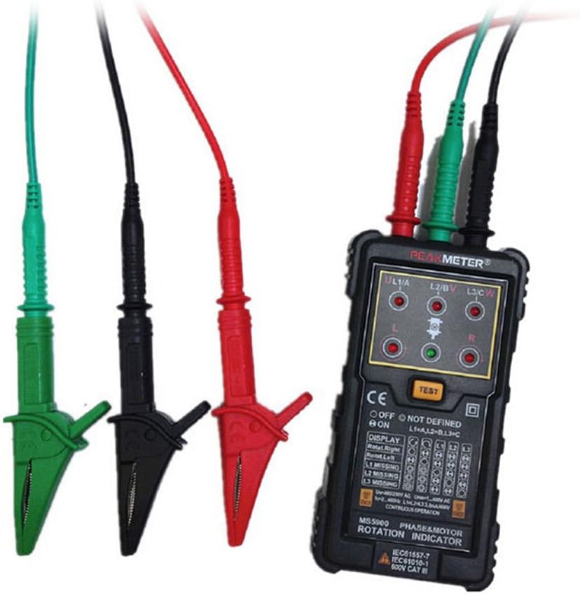
The PEAKMETER MS5900 is a specialized instrument designed to test the magnetic field direction of three-phase systems, phase rotation, and motor rotation direction. This device simplifies the process by allowing determination of motor rotation direction without direct connection of testing lines; simply place the indicator above the motor and align it with the motor drive shaft. It is a durable, reliable, and lightweight handheld tool essential for professionals involved in the installation, repair, or maintenance of three-phase systems and motors.
2. Safety Information
Please read and understand all safety instructions before operating the PEAKMETER MS5900. Failure to follow these instructions may result in electric shock, fire, or serious injury.
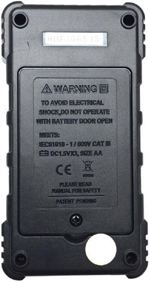
- Electrical Shock Hazard: To avoid electrical shock, do not operate the device with the battery door open. Ensure the battery compartment is securely closed before use.
- Operating Voltage: This device is designed for operating voltages between 120V and 400V AC. Do not use it outside this range.
- Environmental Conditions: Use the device in dry conditions. Avoid exposure to moisture or extreme temperatures.
- Maintenance: Refer to the maintenance section for proper care. Do not attempt to repair the device yourself.
- Compliance: The device meets IEC61557-7, IEC61010-1, and 600V CAT III standards.
3. Product Overview
3.1. Package Contents
The PEAKMETER MS5900 package typically includes the following items:
- PEAKMETER MS5900 Three Phase Rotation Indicator
- Test Leads (Red, Black, Green)
- Alligator Clips (Red, Black, Green)
- User Manual
- Carrying Case (may vary by package)


3.2. Device Features and Controls
The MS5900 features a clear display and intuitive controls for efficient operation.

- U L1/A, L2/B, L3/C Indicators: Red LEDs that illuminate to indicate the presence of voltage on each phase.
- L (Left) / R (Right) Indicators: Red LEDs that illuminate to show the direction of phase rotation.
- TEST Button: Activates the testing function.
- Display Panel: Provides visual feedback on phase rotation (Rotat. Right, Rotat. Left) and missing phases (L1 Missing, L2 Missing, L3 Missing).
- ON/OFF Switch: Located on the side or front panel (indicated by "OFF" and "ON" markings).
4. Setup
4.1. Battery Installation
- Locate the battery compartment on the back of the device.
- Unscrew the battery compartment cover.
- Insert one 9V 6F22 battery, observing the correct polarity.
- Replace the battery compartment cover and secure it with the screw.
- Warning: Do not operate the device with the battery door open.
4.2. Connecting Test Leads
For direct phase rotation testing, connect the provided test leads to the corresponding terminals on the device and to the three-phase system.
- Connect the red test lead to the L1/A terminal.
- Connect the black test lead to the L2/B terminal.
- Connect the green test lead to the L3/C terminal.
- Attach the alligator clips to the other end of the test leads for secure connection to the circuit.
5. Operating Instructions
5.1. Three-Phase Rotation Test (Direct Contact)
- Ensure the device has a fresh 9V battery installed.
- Connect the test leads as described in Section 4.2.
- Turn the device ON.
- Connect the alligator clips to the three phases (L1, L2, L3) of the system you wish to test.
- Observe the U L1/A, L2/B, L3/C indicators. They should illuminate if voltage is present on each phase.
- Press the TEST button.
- The L (Left) or R (Right) indicator will illuminate, and the corresponding "Rotat. Right" or "Rotat. Left" on the display panel will show the phase rotation direction.
- If a phase is missing, the corresponding "L1 Missing", "L2 Missing", or "L3 Missing" indicator will light up.
5.2. Motor Rotation Direction Test (Non-Contact)
The MS5900 can determine motor rotation direction without direct electrical connection.
- Ensure the device is ON.
- Place the PEAKMETER MS5900 directly above the motor's drive shaft.
- Align the device with the motor's axis.
- Start the motor.
- The L (Left) or R (Right) indicator will illuminate, showing the motor's rotation direction.
- Note: For accurate results, ensure the motor is running and the device is positioned correctly.
6. Maintenance
- Cleaning: Wipe the device with a dry, soft cloth. Do not use abrasive cleaners or solvents.
- Battery Replacement: Replace the 9V battery when the low battery indicator appears or if the device does not power on. Always use a fresh battery.
- Storage: When not in use for extended periods, remove the battery to prevent leakage. Store the device in its carrying case in a cool, dry place.
- Inspection: Regularly inspect test leads and alligator clips for any signs of damage or wear. Replace damaged components immediately.
7. Troubleshooting
| Problem | Possible Cause | Solution |
|---|---|---|
| Device does not power on. | Dead or incorrectly installed battery. | Check battery polarity; replace with a new 9V battery. |
| Phase indicators (U L1/A, etc.) do not light up. | No voltage present on the phase; poor connection; damaged test lead. | Verify power supply; ensure secure connections; inspect and replace test leads if damaged. |
| Rotation indicator (L/R) is erratic or incorrect. | Unstable power supply; incorrect connection order; interference. | Ensure stable power; re-check lead connections (L1, L2, L3); minimize electromagnetic interference. |
| "Missing Phase" indicator lights up. | One or more phases are not supplying voltage. | Check the power source for the indicated phase(s). |
| Motor rotation test is inaccurate. | Device not properly aligned with motor shaft; motor not running. | Ensure the device is centered and aligned with the motor shaft; confirm motor is operating. |
8. Specifications
| Parameter | Value |
|---|---|
| Model | MS5900 |
| Operating Voltage | 120V ~ 400V AC |
| Current Consumption | 20mA |
| Frequency Range | 2Hz ~ 400Hz |
| Power Source | 1 x 9V 6F22 Battery |
| Material | ABS+PVC |
| Dimensions | 12.8 cm x 7 cm x 3 cm (5.04 in x 2.76 in x 1.18 in) |
| Weight | 130 g (4.59 oz) |
| Certifications | CE, RoHS, IEC61557-7, IEC61010-1, 600V CAT III |
9. Warranty and Support
For warranty information and technical support, please refer to the documentation provided with your purchase or contact your retailer. Keep your purchase receipt as proof of purchase.
Note: The manufacturer's warranty typically covers defects in materials and workmanship under normal use. Damage resulting from misuse, unauthorized modification, or improper maintenance is usually not covered.


