1. Product Overview
The Allied Telesis AT-X230-28GT-10 is a high-performance, manageable Ethernet switch designed for robust network environments. It features 24 Gigabit Ethernet ports and 4 SFP uplink slots, providing flexible connectivity options for various network devices and fiber optic connections. This switch supports Layer 2 functionality, making it suitable for demanding enterprise and data center applications.
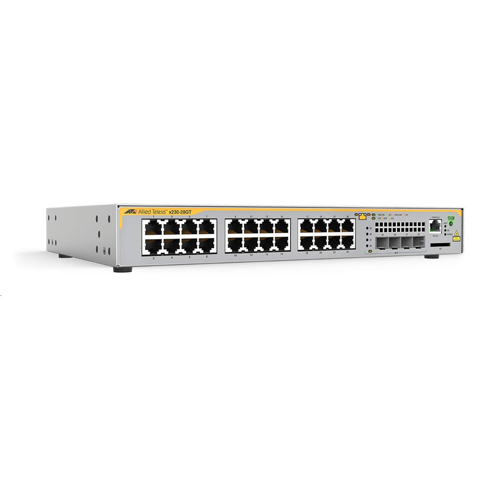
Figure 1: Front Panel of the Allied Telesis AT-X230-28GT-10 Ethernet Switch. This image displays the 24 RJ45 Gigabit Ethernet ports (numbered 1-24), four SFP uplink ports (numbered 25-28), a console port (RS-232), an SD card slot, and various LED indicators for power, fault, link status, and activity.
2. Safety Information
Please read and understand all safety instructions before installing or operating this device. Failure to comply with these instructions may result in injury or damage to the equipment.
- Electrical Safety: Ensure the power source matches the voltage requirements of the switch. Use only the provided power cord or an approved replacement. Do not operate the device with a damaged power cord.
- Ventilation: Maintain adequate airflow around the switch to prevent overheating. Do not block ventilation openings.
- Laser Safety: This product contains a Class 1 Laser. Avoid direct exposure to the laser beam. Do not stare into optical ports or directly view with optical instruments.
- Environment: Install the switch in a clean, dry environment within the specified operating temperature and humidity ranges.
3. Package Contents
Verify that all items are present in the package:
- Allied Telesis AT-X230-28GT-10 Ethernet Switch
- AC Power Cord
- Rackmount Kit (brackets and screws)
- Documentation (Quick Start Guide, Safety Information)
If any items are missing or damaged, contact your vendor immediately.
4. Setup
4.1 Physical Installation
The AT-X230-28GT-10 switch can be installed on a desktop or mounted in a standard 19-inch equipment rack.
- Desktop Installation: Place the switch on a flat, stable surface. Ensure sufficient space for ventilation around the device.
- Rack Mounting: Attach the provided rackmount brackets to the sides of the switch using the included screws. Secure the switch into the equipment rack using appropriate rack screws.
4.2 Power Connection
- Connect the AC power cord to the power inlet on the rear panel of the switch.
- Plug the other end of the power cord into a grounded electrical outlet.
- The switch will power on automatically. Verify the Power LED on the front panel illuminates.
4.3 Initial Network Connection
To access the switch's management interface for initial configuration:
- Console Port (RS-232): Connect a console cable (typically RJ45 to DB9) from your computer's serial port to the CONSOLE port on the switch's front panel. Configure your terminal emulation software (e.g., PuTTY, Tera Term) with the following settings: 9600 bps, 8 data bits, no parity, 1 stop bit, no flow control.
- Network Ports: Connect Ethernet cables from your network devices to the RJ45 ports (1-24) on the switch. For fiber optic connections, insert compatible SFP transceivers into the SFP slots (25-28) and connect fiber optic cables.
5. Operating the Switch
5.1 Power On/Off
The switch powers on automatically when connected to a power source. To power off, disconnect the power cord. For a controlled shutdown, consult the command line interface (CLI) documentation for proper shutdown procedures before disconnecting power.
5.2 LED Indicators
The front panel LEDs provide status information:
- POWER LED: Indicates the power status of the switch. (On: Power is supplied; Off: No power).
- FAULT LED: Indicates a system fault. (On: System fault detected; Off: Normal operation).
- SD LED: Indicates activity on the SD card slot.
- Port LEDs (1-24): Each RJ45 port has two LEDs.
- Link/Activity (ACT): (Green: Link established; Blinking Green: Activity).
- Speed (10/100 LINK or 1000 LINK): (Amber: 10/100 Mbps link; Green: 1000 Mbps link).
- SFP Port LEDs (25-28): Similar to RJ45 port LEDs, indicating link/activity and speed for SFP connections.
- FOX, HDX, COL LEDs: These indicators relate to specific network conditions or features, such as Full Duplex (FOX), Half Duplex (HDX), and Collision (COL) detection. Refer to the detailed product manual for specific interpretations.
5.3 Basic Configuration
After initial connection via the console port, you can configure the switch using the Command Line Interface (CLI). Common initial configurations include:
- Setting the management IP address and subnet mask.
- Configuring a default gateway.
- Setting up user accounts and passwords.
- Enabling remote management (e.g., SSH, HTTPS).
Refer to the Allied Telesis documentation for detailed CLI commands and advanced configuration options.
6. Maintenance
6.1 Cleaning
Regularly clean the exterior of the switch with a soft, dry cloth. Do not use liquid or aerosol cleaners. Ensure ventilation openings are free from dust and obstructions to maintain proper cooling.
6.2 Firmware Updates
Periodically check the Allied Telesis website for firmware updates. Keeping the switch's firmware up-to-date ensures optimal performance, security, and access to new features. Follow the manufacturer's instructions carefully when performing firmware upgrades.
6.3 Environmental Considerations
Ensure the operating environment adheres to the specified temperature and humidity ranges to prevent hardware failure and ensure longevity of the device.
7. Troubleshooting
This section provides solutions to common issues. For more complex problems, consult the detailed troubleshooting guide or contact technical support.
- No Power: If the POWER LED is off, check the power cord connection to both the switch and the electrical outlet. Verify the outlet is functional.
- No Link on Port: If a port's Link/Activity LED is off, check the Ethernet or fiber cable connection. Ensure the connected device is powered on and functioning correctly. Verify the correct SFP transceiver is used for fiber connections.
- Network Connectivity Issues: Verify the switch's IP address, subnet mask, and default gateway settings. Check for correct VLAN configurations if applicable. Ensure connected devices have correct network settings.
- FAULT LED is On: An illuminated FAULT LED indicates a hardware issue. Attempt a power cycle. If the fault persists, contact Allied Telesis technical support.
8. Specifications
Key technical specifications for the Allied Telesis AT-X230-28GT-10 Ethernet Switch:
| Feature | Specification |
|---|---|
| Model Number | AT-X230-28GT-10 |
| Brand | Allied Telesis |
| Number of Ports | 24 x 10/100/1000Base-T (RJ45), 4 x 1000Base-X (SFP) |
| Interface Type | RJ45, SFP |
| Management | Manageable (CLI via RS-232 Console) |
| Supported Layers | Layer 2 |
| Product Dimensions (LxWxH) | 17 x 16 x 6 inches |
| Item Weight | 20.5 pounds (approx. 9.3 kg) |
| Voltage | 48 Volts (DC) - Note: Typically uses an internal AC-DC power supply. |
| Case Material | Plastic |
| Manufacturer | ALLIED TELESIS INC. |
9. Warranty and Support
For detailed warranty information, please refer to the official Allied Telesis website or the warranty card included with your product. Warranty terms and conditions may vary by region and purchase date.
If you require technical assistance or have questions regarding your AT-X230-28GT-10 switch, please contact Allied Telesis technical support through their official website or the contact information provided in your product documentation.