1. Introduction
Thank you for choosing the Avidsen Digital Pocket Multimeter, Model 107100. This manual provides essential information for the safe and efficient operation of your device. Please read these instructions thoroughly before use and retain them for future reference. This multimeter is designed for measuring AC/DC voltage, DC current, resistance, diode and continuity testing, and temperature.
2. Safety Information
Warning: Failure to follow these safety instructions may result in electric shock, fire, or damage to the device.
- Always ensure the multimeter is set to the correct function and range before making measurements.
- Do not attempt to measure voltage or current exceeding the specified maximum limits.
- Exercise extreme caution when working with live circuits. High voltages can be dangerous.
- Inspect test probes for damage before each use. Do not use if insulation is compromised.
- The device features double insulation for enhanced safety. Do not defeat this protection.
- Replace the battery promptly when the low battery indicator appears to ensure accurate readings.
- Only replace the fuse with one of the specified type and rating (0.5A 250V fast-acting).
- Avoid using the multimeter in wet environments or in the presence of explosive gases or dust.
3. Product Overview
The Avidsen Digital Pocket Multimeter is a compact, handheld device designed for various electrical measurements. It features a 3.5-digit LCD display for clear readings and a rotary switch for function selection.
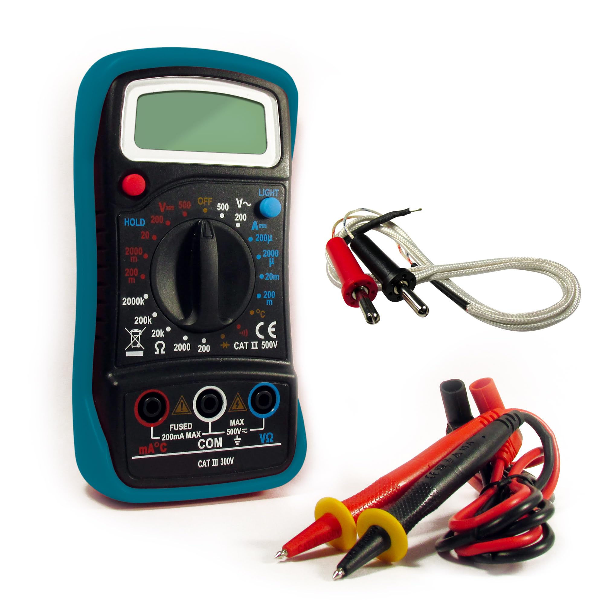
Figure 1: Avidsen Digital Pocket Multimeter, Model 107100. This image shows the front view of the compact multimeter, featuring its LCD display, rotary function switch, and input jacks for test probes.
Key Components:
- LCD Display: 3.5-digit screen for displaying measurement values.
- Function/Range Switch: Rotary dial to select measurement type (Voltage, Current, Resistance, Diode, Continuity, Temperature).
- Input Jacks: Ports for connecting the red and black test probes.
- Test Probes: Insulated leads with sharp tips for making contact with circuits.
- Temperature Probe: (If included) For temperature measurements.
Functions:
- AC/DC Voltage Measurement
- DC Current Measurement
- Resistance Measurement
- Diode Test
- Continuity Test
- Temperature Measurement
4. Setup
4.1 Battery Installation
- Locate the battery compartment cover on the back of the multimeter.
- Use a screwdriver (if necessary) to open the cover.
- Insert the supplied 9V battery, observing the correct polarity (+ and -).
- Replace the battery compartment cover and secure it.
4.2 Connecting Test Probes
- Insert the black test lead into the "COM" (common) input jack.
- Insert the red test lead into the "VΩmA" input jack for voltage, resistance, and current measurements (up to 200mA). For higher current measurements (if applicable to a specific model variant, though this model is pocket-sized and typically limited), refer to specific markings.
- Ensure the connections are firm and secure.
5. Operating Instructions
Before taking any measurement, ensure the multimeter is correctly set up and the test probes are securely connected. The measurement sequence is approximately 2 times per second.
5.1 Measuring AC/DC Voltage
- Turn the function switch to the desired ACV (Alternating Current Voltage) or DCV (Direct Current Voltage) range. Start with the highest range if the voltage is unknown.
- Connect the test probes in parallel across the component or circuit to be measured.
- Read the voltage value on the LCD display.
5.2 Measuring DC Current
- Warning: To measure current, the multimeter must be connected in series with the circuit. This requires breaking the circuit.
- Turn the function switch to the desired DCA (Direct Current Amperes) range.
- Open the circuit where current is to be measured.
- Connect the red probe to the higher potential side and the black probe to the lower potential side of the break in the circuit.
- Read the current value on the LCD display.
5.3 Measuring Resistance
- Warning: Ensure the circuit or component is completely de-energized before measuring resistance.
- Turn the function switch to the desired Ohm (Ω) range.
- Connect the test probes across the component whose resistance is to be measured.
- Read the resistance value on the LCD display.
5.4 Diode Test / Continuity Test
- Warning: Ensure the circuit or component is completely de-energized.
- Turn the function switch to the Diode/Continuity (symbol often looks like a diode and a sound wave).
- Diode Test: Connect the red probe to the anode and the black probe to the cathode of the diode. A forward voltage drop will be displayed. Reverse the probes; an open circuit (OL) should be displayed.
- Continuity Test: Connect the probes across the circuit or component. If continuity exists (low resistance), the multimeter will emit an audible beep and display a low resistance value.
5.5 Measuring Temperature
- If your multimeter includes a temperature probe, connect it to the appropriate input jacks (refer to specific markings if different from VΩmA/COM).
- Turn the function switch to the Temperature (°C or °F) setting.
- Place the tip of the temperature probe on or near the object whose temperature is to be measured.
- Read the temperature value on the LCD display.
6. Maintenance
6.1 Cleaning
Wipe the multimeter casing with a damp cloth and mild detergent. Do not use abrasive cleaners or solvents. Ensure the device is powered off and probes are disconnected before cleaning.
6.2 Battery Replacement
When the low battery indicator appears on the display, replace the 9V battery as described in Section 4.1. Always use a fresh 9V battery.
6.3 Fuse Replacement
If the current measurement function stops working, the fuse may need replacement. Ensure the multimeter is off and probes are disconnected. Open the casing (refer to the battery compartment or specific fuse access if different) and replace the fuse with a 0.5A 250V fast-acting type. Never use a fuse with a different rating.
6.4 Storage
When not in use for extended periods, remove the battery to prevent leakage. Store the multimeter in a cool, dry place, away from direct sunlight and extreme temperatures.
7. Troubleshooting
| Problem | Possible Cause | Solution |
|---|---|---|
| No display or faint display | Low or dead battery | Replace the 9V battery. |
| Incorrect readings | Incorrect function/range selected; poor probe contact; damaged probes | Verify function/range; ensure firm probe contact; inspect and replace damaged probes. |
| Current measurement not working | Blown fuse | Replace the 0.5A 250V fast-acting fuse. |
| "OL" (Overload) displayed | Measurement exceeds selected range or maximum input | Select a higher range or ensure measurement is within device limits. |
8. Specifications
- Model Number: 107100
- Manufacturer: Avidsen
- Display: 3.5-digit LCD
- Measurement Rate: Approximately 2 times per second
- Power Source: 9V battery (supplied)
- Fuse: 0.5A 250V fast-acting
- Dimensions (L x W x H): 14 cm x 5.5 cm x 4 cm (5.5 x 2.2 x 1.6 inches)
- Weight: 150 grams (approx. 5.3 oz)
- Features: Double insulation, overload protection, low battery indicator
- Functions: AC/DC Voltage, DC Current, Resistance, Diode Test, Continuity Test, Temperature
- Country of Origin: China
9. Warranty and Support
Avidsen products are manufactured to high-quality standards. For information regarding warranty coverage, technical support, or service, please refer to the warranty card included with your purchase or visit the official Avidsen website. Please have your model number (107100) and purchase date available when contacting support.


