
1. Product Overview
The Johnson Controls A421 Series Electronic Temperature Control is a single-stage control unit designed for precise temperature management. It features a single-pole, double-throw (SPDT) output relay, making it suitable for both heating and cooling applications. The device includes a backlit LCD with adjustable brightness and a three-button touchpad for user interaction. An LED indicator provides visual feedback on the output relay's status.
Key features include:
- Single-stage control operation.
- Single-pole, double-throw (SPDT) relay output.
- Temperature control range: -40 to 212°F (-40 to 100°C).
- Bright backlit LCD display with adjustable brightness.
- Three-button touchpad interface with user adjustment restriction capability.
- Adjustable anti-short cycle delay.
- Temperature setback function.
- Sensor offset capability for calibration.

Figure 1: Front view of the A421 Electronic Temperature Control, showing the LCD display and control buttons.
2. Setup and Installation
Proper installation is crucial for the safe and effective operation of the A421 temperature control. It is recommended that installation be performed by a qualified technician in accordance with all local and national electrical codes.
2.1 Mounting
Mount the control unit in a location that is easily accessible for wiring and viewing the display. Ensure the mounting surface is stable and free from excessive vibration or moisture. The unit is designed for surface mounting.
2.2 Wiring
The A421 features a single-pole, double-throw (SPDT) output relay. Carefully follow the wiring diagram provided in the official product documentation. Ensure all connections are secure and properly insulated. The unit requires a power supply and connections for the temperature sensor and the controlled load (e.g., heating element, cooling compressor).
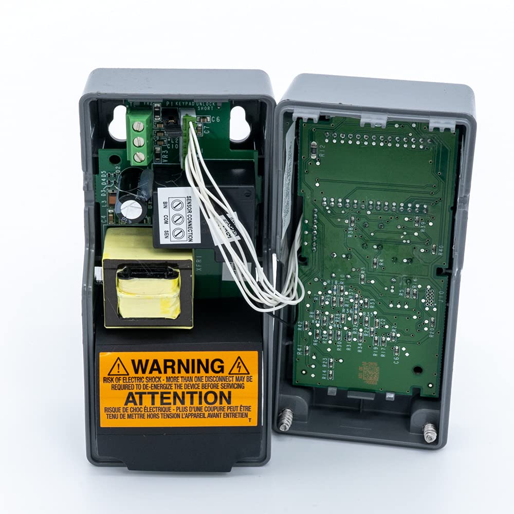
Figure 2: Internal view of the A421 control unit, illustrating the wiring terminals for power, sensor, and relay output. WARNING: Risk of electric shock. More than one disconnect may be required to de-energize the device before servicing.
For detailed wiring diagrams and installation instructions, please refer to the official product manual available at: Johnson Controls A421 Series Product Manual (PDF).
3. Operating Instructions
The A421 control unit is operated via a three-button touchpad and an LCD display. The display shows the current temperature and various menu options.
3.1 Basic Operation
- Power On: Once wired and powered, the LCD will illuminate and display the current temperature.
- Temperature Display: The primary screen shows the measured temperature.
- LED Indicator: An LED on the unit indicates the ON/OFF status of the output relay.
3.2 Setting Temperature and Parameters
Accessing and adjusting settings is done through the MENU button and arrow keys. The A421 allows for setting on and off temperatures for heating or cooling, adjusting the anti-short cycle delay, configuring temperature setback, and applying a sensor offset.
- Press the MENU button to enter the main menu.
- Use the UP and DOWN arrow buttons to navigate through the menu options.
- Press MENU again to select an option or confirm a setting.
- Adjust values using the UP and DOWN arrow buttons.
- Press MENU to save the new setting and exit the parameter.
Refer to the detailed programming guide in the official manual for specific parameter codes and advanced settings, including restricting user adjustments.
4. Maintenance
The Johnson Controls A421 is designed for reliable operation with minimal maintenance. Regular checks can help ensure its longevity and accuracy.
4.1 Cleaning
Keep the unit's exterior clean. Use a soft, damp cloth to wipe the display and casing. Do not use abrasive cleaners or solvents, as these can damage the plastic and LCD screen.
4.2 Sensor Inspection
Periodically inspect the temperature sensor and its cable for any signs of damage, such as cuts, kinks, or corrosion. A damaged sensor can lead to inaccurate readings or unit malfunction. The sensors are designed to be interchangeable, allowing for replacement if necessary.

Figure 3: Side view of the A421, highlighting the temperature sensor and its cable connection.
4.3 Wiring Connections
Ensure all wiring connections remain tight and secure. Loose connections can cause intermittent operation or damage to the unit.
5. Troubleshooting
If the A421 unit is not functioning as expected, consult the following common troubleshooting steps before contacting support.
| Problem | Possible Cause | Solution |
|---|---|---|
| Unit does not power on / LCD is blank. | No power supply; incorrect wiring; internal fuse (if applicable). | Check power source and circuit breaker. Verify wiring connections according to the manual. Consult a qualified electrician if issues persist. |
| Display shows "sF" or other error codes. | Sensor fault or disconnection. | Check the sensor cable for damage and ensure it is securely connected to the unit. Replace the sensor if it is faulty. |
| Inaccurate temperature readings. | Sensor placement; sensor offset setting; faulty sensor. | Ensure the sensor is placed correctly to measure the desired temperature. Check and adjust the sensor offset parameter. If necessary, replace the sensor. |
| Relay not switching as expected. | Incorrect setpoint; anti-short cycle delay active; wiring issue. | Verify temperature setpoints and differential settings. Check if the anti-short cycle delay is preventing immediate switching. Inspect relay wiring. |
For a comprehensive list of error codes and advanced troubleshooting, refer to the official Johnson Controls A421 Series product manual.
6. Specifications
The following table outlines the technical specifications for the Johnson Controls A421ABC-02C Electronic Temperature Control.
| Specification | Value |
|---|---|
| Model Number | A421ABC-02C |
| Temperature Range | -40 to 212°F (-40 to 100°C) |
| Output Relay | Single-Pole, Double-Throw (SPDT) |
| Display Type | Backlit LCD |
| Control Type | Single-stage |
| Product Dimensions | 11.1 x 4.1 x 4.3 inches |
| Item Weight | 1.15 Pounds |
| Manufacturer | Johnson Controls |
| UPC | 645220630707 |
7. Warranty and Support
7.1 Warranty Information
Johnson Controls products are manufactured to high-quality standards. For specific warranty terms and conditions, please refer to the documentation included with your product or visit the official Johnson Controls website. Standard warranty typically covers defects in materials and workmanship for a specified period from the date of purchase.
Extended protection plans may be available for purchase to provide additional coverage beyond the standard warranty period. For example, 3-Year and 4-Year Protection Plans are often offered for this product.
7.2 Customer Support
For technical assistance, product inquiries, or warranty claims, please contact Johnson Controls customer support. Contact information can typically be found on the manufacturer's official website or in the product packaging.
You can also find comprehensive resources, including the full product manual, on the Johnson Controls website:
- Official Product Manual (PDF): http://cgproducts.johnsoncontrols.com/MET_PDF/2476643019.pdf
- Johnson Controls Official Website: https://www.johnsoncontrols.com/


